Cellular Internet of Things for Practitioners by R. Vahidnia and F. John Dian is licensed under a Creative Commons Attribution-NonCommercial-ShareAlike 4.0 International License, except where otherwise noted.
© 2021 R. Vahidnia and F. John Dian
The Creative Commons licence permits you to retain, reuse, copy, redistribute, and revise this book—in whole or in part—for non-commercial purposes for free providing all shared copies and revisions are shared under the same licence and the authors are attributed as follows:
Cellular Internet of Things for Practitioners by R. Vahidnia and F. John Dian is used under a CC BY-NC-SA 4.0 Licence.
Sample APA-style citation (7th Edition):
Vahidnia, R., & Dian, F. J. (2021). Cellular Internet of Things for Practitioners. British Columbia Institute of Technology. https://pressbooks.bccampus.ca/cellulariot/
All images are © R. Vahidnia and F. John Dian and shared under a CC BY-NC-SA 4.0 Licence.
Ebook ISBN: 978-1-990132-01-8
Print ISBN: 978-1-990132-00-1
Publisher: BCIT
Publication date: January 30, 2021
The authors and publisher of this book have used their best efforts in preparing this book. These efforts include the development, and research of the theories, technologies and standards. The authors and publisher make no warranty of any kind, expressed or limited, with regards to the documentation contained in this book.
Dedicated to
our loving parents
F. John Dian is a faculty at the Department of Electrical and Computer Engineering at British Columbia Institute of Technology (BCIT) in Vancouver, Canada. He received his Ph.D. degree from Concordia University, Montreal, Canada in Electrical and Computer Engineering in 2004. Dr. Dian has more than 20 years of experience in design and implementation of telecommunication circuits and systems. Dr. Dian holds a certificate in business analytics from Harvard University, USA and co-chairs the center of excellence for analytics at BCIT. He has been recognized with several excellence in teaching and research awards. Dr. Dian is a senior member of the Institute of Electrical and Electronics Engineers (IEEE) and an active member of Association of Engineers and Geoscientists of British Columbia .
Reza Vahidnia is a faculty at the Department of Electrical and Computer Engineering at British Columbia Institute of Technology (BCIT) in Vancouver, Canada. He received his Ph.D. degree from Ontario Tech University, Oshawa, Canada in Electrical and Computer Engineering in 2014. He has served as a senior IoT analyst at Rogers Communications Inc., and as an IoT project manager at TELUS where he worked on several smart city and IoT initiatives. Dr. Vahidnia is a professional engineer (P.Eng) and an active member of the Association of Engineers and Geoscientists of British Columbia (APEGBC).
In today’s Internet of Things (IoT) ecosystem, Low-power Wide-area (LPWA) communication technologies play a central role in connecting the smart objects to the Internet due to their low complexity, low power consumption, wide coverage and high capacity. Cellular IoT technologies such as LTE-M and NB-IoT bring significant value for LPWA use cases over non-cellular communications due to their ubiquitous connectivity, technology maturity, scalability, reliability and security.
This book, first describes the simplified architecture of an IoT network from the core functional perspective, then presents step-by-step procedures to establish a connection between the IoT device and platform. It practically shows how to connect a cellular IoT module to the Microsoft Azure IoT Hub using the LTE-M technology.
Four experiments are designed to practice different concepts required to exchange the data between the IoT device and the software backend. In Chapter 2, the required hardware and AT commands to configure the LTE-M module are described. This chapter will also show how to send text messages and enable the GPS module to acquire the positioning information.
The purpose of Chapter 3 is to configure the LTE-M module as a TCP/IP client in order to establish a client-server connection with a server and exchange data.
After becoming familiar with various IoT application protocols in Chapter 4, the MQTT function lab will show how to configure the LTE-M module to act as a MQTT client/subscriber and exchange data with a broker. The broker will be built on a computer using Node-RED programming tool to wire together hardware devices, and online services to establish a communication with the LTE-M module. The data published on the broker will be sent to the MQTT clients that have subscribed to the topic.
Finally, Microsoft Azure IoT Hub is introduced which is a cloud managed service acting as a central message hub for two-way secure communication between the IoT application and the IoT device it manages. In Chapter 6, you will learn how to use the Node-RED flow to establish a connection between the Microsoft Azure IoT platform and the IoT device. Once the data is received by Microsoft Azure, different components can be utilized to visualize and analyze the data to create actionable insight.
The Internet of Things (IoT) has connected billions of sensors and devices and created many opportunities that led many businesses to initiate IoT marketing and development budgets. Affordable, smaller and more powerful hardware, ubiquitous connectivity, availability of big data tools and cloud-based services, and huge market awareness are some of the reasons why more and more IoT opportunities and use cases are occurring [1]. To bring these many use cases and opportunities to life and handle the huge amount of data generated by massive number of IoT devices and sensors, a solid infrastructure and architectural model is needed. From a network architectural standpoint, the simplified core IoT functional stack has four main layers as shown in Figure 1.1.
Note that security is an essential element of each building block of this IoT technology stack.
Hardware is where the data is collected and includes the smart objects (Things) with built-in sensors to measure physical data, actuators to perform tasks, low cost microprocessor, communication device to receive instructions, send or route data, and a power source (battery, mains, solar, etc.).
The characteristics and type of the smart objects in the hardware layer and their requirements can determine the technologies and protocols of the upper layers in the IoT functional stack. Battery-powered smart objects can have high mobility and require wireless technologies for their communications. However, their transmission range or reporting frequency could be limited. On the other hand, power-connected things are typically static and they are allowed to use technologies and protocols with higher power consumption that can provide longer transmission range and report their data more frequently. The amount and type of data collected by the smart objects and exchanged during the report cycles have an impact of the power consumption and consequently the choice of the connectivity technologies and protocols. For example, the electroencephalogram (EEG) signals collected by a smart helmet are richer compared to the data collected by a simple temperature sensor and hence, require more power and throughput to transmit the data.
Another important characteristic of a smart object is its report range or basically how far the data needs to be transmitted. For example, a vibration sensor installed on the train rails in a rural area may need to communicate with a cellular tower a few hundred meters away. Thus, for such a use case with a long report range, a low power communication technology is required to cover a wide area network.
The aforementioned hardware examples show that in order to design an IoT solution, a first step could be to examine the requirements of the “Thing” in terms of power consumption, report range, mobility, frequency of report and data transmission rate [2].
The connectivity or communications layer connects the smart object (hardware) to the network through an IoT access technology (e.g., WiFi, Bluetooth, etc.). Basically, the connectivity layer is responsible to transport the collected data from the sensors to the Internet through different access technologies with fundamentally different architectures, data transmission rates, report range, power consumption and security requirements. The majority of the existing IoT devices use one of the following forms of data transfer infrastructure shown in Figure1.2 to communicate with the software backend (cloud services) where the data and all connected devices are managed.
In this unlicensed short-range communication model, the “Thing” is connected to the Internet through a user-provided communications gateway or a vendor managed mesh network. In the user-provided architecture, the connectivity of smart object to the software backend (cloud or data storage infrastructure) is provided by technologies such as Bluetooth or WiFi that operate in the unlicensed spectrum. Although such technologies have high data transmission rates, security, provisioning and device management problems (e.g., different WiFi standards and security models, passwords change etc.) are major barriers to extend these technologies into industrial and enterprise use cases. Moreover, the high power consumption (limited battery life cycle of the IoT devices and higher maintenance costs) and low reporting range of such ad-hoc networks could be other barriers to adopt these unlicensed spectrum technologies in a broader range of IoT use cases.
In vendor managed mesh networks, communication protocols such as ZigBee or Z-Wave are deployed to transmit the collected data into a gateway which then forwards the received data into the software backend usually via cellular networks (4G/LTE). In these conventional costly and power hungry solutions, different libraries need to be set up for each different type of simple or complex smart object to integrate them into the IoT platform [1].
LoRa and Sigfox are two low power, widely used and relatively cheap IoT technologies intended for battery operated smart objects with high report range (wide area networks). These unlicensed spectrum technologies target key IoT requirements such as secure bi-directional communications, mobility and localization services; however, their low data rate limits the capability to update the firmware and send complex commands. The maximum data rates for LoRa and Sigfox are 27kbps and 100bps, respectively. Interference in high volume industrial applications is another issue in deploying these technologies. Moreover, the costly deployment of the technology and the need to set up a physical network infrastructure is another barrier in adoption of these alternative solutions.
One main important advantage of the cellular technologies over other unlicensed LPWA access technologies is their ubiquitous connectivity. The cellular networks are almost always available even in remote locations. Cellular IoT (CIoT) technologies are highly reliable, secure, and scalable which makes them suitable candidate technologies for massive IoT where a huge number of smart objects (up to 1 million devices per km2) are connected to the Internet. Moreover, cellular communications’ maturity provides global ecosystem interoperability for CIoT technologies.
The 3rd Generation Partnership Project (3GPP) – a global technical body which develops technical specifications for mobile communication system – introduced a suite of two complementary CIoT technologies called enhanced Machine-Type Communications (eMTC or LTE-M), and Narrow band Internet of Things (NB-IoT) in its Release 13 [3].
LTE-M is a low‑power wide‑area (LPWA) air interface in the licensed spectrum that lets IoT devices connect with a data rate up to 1Mbps [4]. Thanks to two innovations of LTE Cat-M1 introduced by 3GPP Release 13, Power Saving Mode (PSM) and extended Discontinuous Reception (eDRx) longer battery lifecycles (up to a few years) are enabled and greater in‑building range is supported as compared to standard cellular technologies such as 3G or LTE Cat 1. The power efficient LTE-M also supports voice functionality via VoLTE (used for applications requiring a level of human interaction), as well as full mobility and in‑vehicle hand‑over (used for asset tracking applications).
NB-IoT uses a small bandwidth for data transmission and reduces the bandwidth to 200 kHz (180 kHz plus guard-band) as compared to 1.4 MHz used in LTE-M [3]. Also, compared to LTE-M, NB-IoT consumes less power (longer battery life cycle) and provides even deeper coverage. The reduced complexity of NB-IoT makes it suitable for low data rate (10’s of kbps), delay-tolerant use cases including sensors and meters.
Software backend consists of cloud services that manage the network and the IoT devices. The integration of data and the interface to the 3rd party systems such as Enterprise Resource Planning (ERP) systems are provided by these cloud services. IoT platforms such as Microsoft Azure IoT Hub, Amazon Web Services (AWS) IoT, IBM Watson IoT are part of the central software backend. Event processing and action management, advanced analytics, privacy management, storage/database, device management, and integration with external interfaces are some of the functionalities of the IoT platforms.
The application layer visualizes the collected data from the sensors in real-time and integrates the business systems. This is how the raw collected data from the sensors is turned into value for businesses and companies. Moreover, the behavior of the smart things is controlled by the commands sent from the application layer to the smart objects.
Typically, there are two types of analytics in the application layer that generate two different intelligent views about the IoT system and the IoT network. First, data analytics which provides insight about the IoT system through analysing and processing the data collected by the sensors. Second, network analytics that evaluates the connectivity of the network to maintain the quality of service and prevent future network failures. The IoT network architect determines the depth of the network analytics depending on the use case. For use cases such as environmental monitoring where the sensors occasionally transmit their collected data without the need for an immediate action, a basic network analytics could be sufficient. On the other hand, in mission critical use cases such as connected vehicle, it is extremely impotent to have a detailed view of the network connectivity and performance.
In the previous chapter, we briefly discussed different building blocks (layers) of an IoT solution from the core functional perspective. In this chapter and the next few chapters, we will discuss how to practically work with an LTE-M module to establish a CIoT connectivity scheme to transfer the data to the Internet. The high level architecture of the IoT project that we want to complete in this book is described in Figure2.1.
In this project, we will be using a Quectel BG96 LTE-M modem to exchange the data with the Internet through the cellular tower. The transmitted data is then stored and analyzed in the software backend (cloud platform) that gives full accessibility to the user to monitor, control and manage the device and network.
Following the step-by-step instructions in this chapter, you will become familiar with the TELUS IoT Starter Kit and Avnet Quectel BG96 LTE Cat-M1/NB-1 Shield. Also, you will be able to configure the Quectel BG96 modem using AT commands (instructions used to control a modem). Moreover, you will learn how to enable the GPS and acquire the location information using the AT commands.
In these lab series, you will learn how to create, prototype and develop an IoT product using the TELUS LTE-M IoT Starter Kit. You will practice how to connect to the LTE-M network (The modem supports both LTE-M and NB-IoT. However, in this book, you will only work with LTE-M). Then, you will use Microsoft Azure cloud services to manage, store and analyze the data. The starter kit integrates three stacked boards as shown in Figure 2.2. A brief introduction of each board is given here. Note that in this book you will only work with the BG96 module (top board) in the standalone mode.
BG96 is a series of ultra low-power (approximately 10 µA in PSM mode) dual-mode LTE Cat-M1/Cat-NB1/EGPRS module manufactured by Quectel Wireless Solutions. The maximum uplink (UL) and downlink (DL) data rates for this module are 375kbps and 300kbps, respectively. This module is certified by the major mobile network operators in the world (TELUS, Bell and Rogers in Canada) and has wide range of IoT use cases such as asset tracking, smart cattle, etc.
The module includes the BG96 modem and is equipped with some additional features such as SIM holder, Arduino shield interface (connectors compatible with Arduino extension boards such as WiFi), LTE and GPS antenna SMA connectors, USB port and configuration switches.
The IKS01A2 Sensor Board contains the following sensors:
The communication between this sensor board the MCU board (NUCLEO-L496ZG) is through I²C interface.
Figure2.5 shows the NUCLEO-L496ZG Microcontroller Board with Arduino connectors. You can consider connecting the BG96 module to this MCU board for future IoT products.
Note that in this book our focus is only on the BG96 module and we will not connect the sensor and the microcontroller boards to build the stack. If you are interested, you can build the full stack and try to send the AT commands to the BG96 module through the microcontroller board.
In this sub-section, we discuss how to activate the SIM card for TELUS network operator. Different mobile network operators have different procedures to activate their SIM cards. If you already have an activated SIM card, skip this sub-section.
Before activating the TELUS SIM card, you need to have two codes handy:
In this part of the lab you will work with the BG96 board on its own and when it is not stacked to the MCU board.
AT commands (AT is the abbreviation of ATtention) are instructions used to control a modem and start with “AT”. Quectel_BG96_AT_Commands_Manual contains a full set of BG96 modem AT commands.
ATI // Display Product Identification Information
Quectel
BG96
Revision: BG96MAR02A07M1G
OK
AT GSN // Request International Mobile Equipment Identity (IMEI). Note that IMEI is a unique 15-digit identification or serial number of the module.
866425033446404
OK
AT CFUN=1 // Set Phone Functionality as Full
OK
AT QCCID // Show the SIM card’s Integrated Circuit Card Identifier (ICCID) number
QCCID: 8912230100074759513F
OK
AT COPS=0 // Automatic Operator selection
OK
AT QCFG=”NWSCANSEQ”,020301 // Configure Radio Access Technologies (RAT) searching sequence
02: LTE-M
03: NB-IoT
01: GSM
OK
AT QCFG=”IOTOPMODE”,0 // Configure network category to be searched under LTE RAT.
0: LTE Cat M1
1: LTE Cat NB1
2: LTE Cat M1 and Cat NB1
OK
AT QCFG=”BAND”,0,80A,80A // Band configuration. Specify the frequency bands allowed to be searched of User Equipment (UE). The hex number represent the GSM, LTE-M and NB-IoT band values, respectively.
0: not to change frequency band.
80A : LTE B2 LTE B4 LTE B12
OK
AT CSQ // Signal quality report. Indicate the received signal strength indicator (RSSI) and the channel bit error rate (BER). For example the first received number (23) means the RSSI is -67 dBm and the second number (99) shows the channel bit error rate in percent.
0: Less than or equal to -113dBm
1: -111dBm
2…30: -109… -53dBm
31: Greater than or equal to -51dBm
99: Not known
CSQ: 23,99
OK
AT COPS=? // Operator Status.
0: Unknown
1: Available
2: Current operator
3: Forbidden
As you see in the response from the module the status for TELUS is 2 which means it is the current operator.
COPS: (1,”Bell”,”Bell”,”302610″,8),(1,”Rogers Wireless”,”ROGERS”,”302720″,8),(1,”Rogers Wireless”,”ROGERS”,”302720″,0),(2,”TELUS”,”TELUS”,”302220″,8),,(0,1,2,3,4),(0,1,2)
OK
AT QGPS=1 // Turn on GNSS OK AT QGPSLOC? // Acquire positioning information QGPSLOC: 012102.0,4919.1986N,12305.5925W,3.2,-19.0,2,177.06,0.0,0.0,230220,08 OK AT QGPSEND // Turn off GNSS OK |
Note: If you are running the lab in a building, after you enter AT QGPSLOC?, you may get “ CME ERROR: 516”. This error means the modem has not received a GPS fix yet. You can wait for a few more minutes or move the GPS antenna near a window or outside. Note that a GPS fix is the locational information that the GPS system provides for a specific point.
If your carrier connectivity subscription includes SMS text messaging you will be able to send a text message using AT commands.
AT CMGF=1 // SMS message format is set as text OK AT CSCS=“GSM” // Character set is GSM OK AT CMGS=“12369912020” // Destination phone number > Hello, this is a test. // Enter your message and then press CTR-Z to send CMGS: 5 // Message reference upon successful delivery OK |
In this chapter, we would like to connect the BG96 board to the Internet to send and receive data. For this purpose, the BG96 board needs to establish a TCP/IP connection to a server. This can be done by using a software program such as SocketTest to enable the computer to act as a server. The configuration used in this lab is shown in Figure3.1.
For the BG96 board to communicate with the server installed on the computer, the BG96 board sends the data to the IP address of the computer. If the computer is installed behind a Network Address Translation (NAT) router like the ones in most homes and offices, the computer may use an internal address. For proper communication to take place, the NAT router needs to work well and proper port forwarding needs to be configured.
Quectel BG96 module can access to the Internet using the embedded TCP/IP stack and AT Commands. The module supports services for UDP client/server and TCP client/server. In this lab, the BG96 module will act as a TCP client and connects to a TCP server to exchange data.
To start using TCP/IP AT Commands, first you need to configure the parameters of the context such as the APN, username, and password. Second, the Packet Data Protocol (PDP) context which is is the connection between the modem and the end address is activated. Third, you will start a socket service to exchange data. Finally the socket service is closed and PDP context is deactivated.
In this part of the lab, you will set up a TCP/IP server on your computer to be able to communicate with the BG96 module.
The Default Gateway is the IP address of the interface of your ISP router connected to your PC. IPv4 address is the private IP address given to your PC by the router. Since the private IP address is not addressable from outside your network, using “port forwarding”, you can tell your router where to direct traffic for a specific port on your PC. In other words, port forwarding allows a remote computer on a different network (e.g., BG96 module) to connect to your PC on a private network and run a service behind the router.
In this part of the lab, you will set up a TCP client connection to enter into buffer access mode. BG96 TCP/IP AT Commands Manual has the full list and description of different modes and commands required for TCP/IP connections.
AT QICSGP=1,1,”M2M-WEST.TELUS.IOT”,””,””,1 // Set the your mobile carrier APN OK |
AT QIACT=1 // Activate a context OK
AT QIACT? // query the context state QIACT: 1,1,1,”10.200.109.166″ OK |
AT QIOPEN=1,0,”TCP”,”172.218.32.19″,350,0,0 // Set up a TCP client connection using your own public IP address OK
QIOPEN: 0,0 |
AT QISEND=0 // Send changeable length data. After text press CTR Z to send. > Hello, this is a test SEND OK |
QIURC: “recv”,0 // Send changeable length data. After text press CTR Z to send. AT QIRD=0,1500 QIRD: 30 Hi, I received your message.
OK |
The instructions above explained how to establish a TCP client connection using the BG96 module. If you are interested, referring to BG96 TCP/IP AT Commands Manual you can try establishing UDP client, TCP server and UDP server connections.
D. Connectivity to the Internet
To check the connectivity between BG96 board and the Internet, we send ping commands. Since ping uses TCP/IP connection, the success of the command below shows that your board is capable of making TCP/IP connection and you can check the connectivity.
AT QPING=1, “www.bcit.ca”
Massive IoT interconnects an enormous number of devices and services over the Internet for a broad range of applications. The IoT devices are typically connected to the Internet via Internet Protocol (IP).
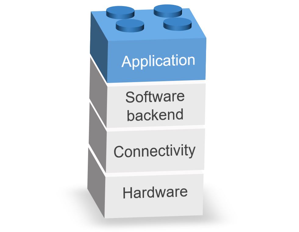
The application-layer protocols such as HyperText Transfer Protocol (HTTP) are primarily used for communication on browser-based clients, which typically run on relatively high-capability devices, such as smartphones that use relatively high-bandwidth communications channels (e.g., LTE). On the other hand, IoT protocols are set of rules suitable for IoT applications to ensure that data sent from an IoT device gets read and understood by another device. IoT protocols also need to ensure optimum security of the exchanged information between connected devices. Depending on the IoT devices and their applications, there are different application-layer IoT protocols. The application layer is actually an interface between the user and the IoT device. A specific IoT use case may require a specific application-layer data communication protocol and an IoT-centric communications stack.
There are many IoT protocols available to choose for different applications and requirements. For example, some of these protocols are specifically designed to satisfy the requirements for fast and reliable business transactions or some other are optimized to meet the requirements of data collection such as sensor updates in constrained networks. Some other IoT protocols are suitable for applications where Instant Messaging (IM) and online presence detection is needed [5]. Each of these protocols have their own advantages and disadvantages when dealing with different IoT scenarios. This is why it is important to understand the characteristics of various IoT protocols to be able to choose the best-fil protocol for your use case.
Three widely accepted and key IoT protocols include Message Queue Telemetry Transport (MQTT), Constrained Application Protocol (CoAP), and Advanced Message Queuing Protocol (AMQP). We first introduce each of these three protocols in detail and then present a general comparison between them to gain insight into the strengths and limitations of each protocol.
MQTT is a lightweight and scalable publish/subscribe IoT messaging protocol that can be easily implemented to relay data through a central server called the broker. This protocol is primarily used for constrained networks that provide connections to remote locations and is ideal for small devices that require efficient bandwidth and battery use such as car sensors, smoke detectors, smart watches, and text-based messaging applications. Compared to HTTP, MQTT is faster, has less overhead and power consumption. The other difference to HTTP is that in MQTT, a client does not have to pull the information it needs, but if there is new data to be sent, the server (broker) pushes the information to the client.
In MQTT, new devices can be easily added without touching the existing infrastructure (multiple publishers and multiple subscribers). Since the new devices only communicate with the broker, they do not need to be compatible with the other devices.
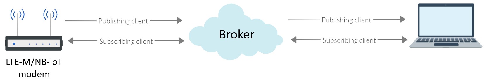
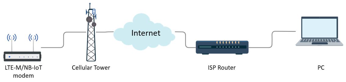
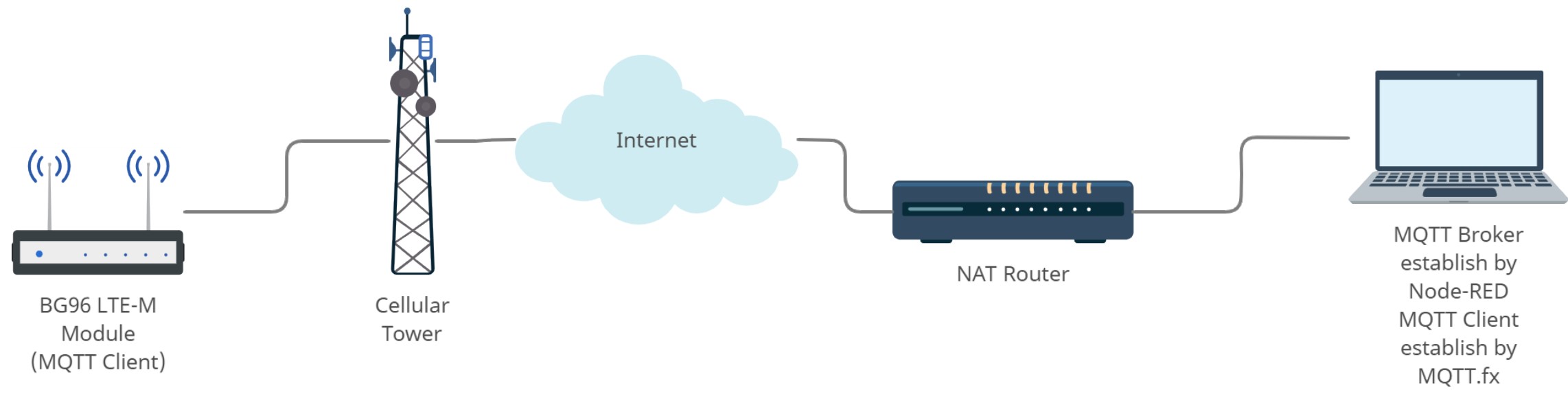
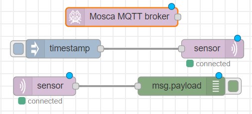
The broker acts like a post office. Instead of a device, sending the messages to or getting them from another device directly (peer-to-peer), the client (publisher) sends the messages to the post office (broker) and then it is forwarded to everyone who needs the message (subscribers). The difference is that MQTT uses subject line called “topic” instead of addresses i.e., everyone who needs a copy of that message subscribes to that topic. A topic is a simple string that can have more hierarchy levels, which are separated by a slash (e.g. sensors/temperature). Note that topics are case sensitive.
In MQTT, the IoT devices are interconnected via the broker, meaning that there is no direct connection between clients and the broker relays the messages between clients. Unlike most communication protocols, this message relay is not restricted to a one-to-one model. The message uses a topic for unique identification and is not targeted into a single device. Hence, it is possible to have many devices subscribe to the same topic, which can realize a one-to-many model. Similarly, a many-to-many model multiple devices can be publishing the same topic and have one or multiple subscribers. The broker handles all of these scenarios by using topics to manage the messages.
MQTT is a bi-directional communication protocol where each client can both produce and consume data by publishing messages and subscribing to topics. The big advantage of this two-way communication is that the IoT devices can send sensor data and at the same time receive configuration information and control commands.
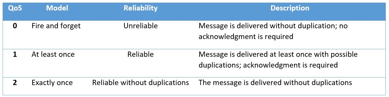
MQTT uses three levels of Quality of Service (QoS) to ensure its message reliability. Table4.1 shows these three QoS levels including fire and forget (Level 0), acknowledged delivery (Level 1), and assured delivery (Level 2).
Table4.1. MQTT QoS levels
MQTT requires reliable, lossless, and in-order delivery of packets, and thus, it is a TCP/IP-based protocol where a TCP connection needs to be established prior to transferring the data. MQTT is a three-phase handshake communication that needs to first establish the TCP connection. Second, the MQTT connection is established and data is published. Finally, the TCP connection is terminated.
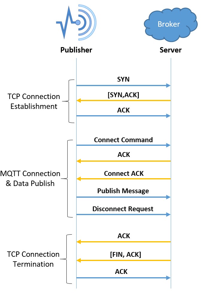
A three-way handshake is used to establish the TCP connection. First, the client sends SYN request to indicate that it wants to communicate with the server (broker) which is always in the listening mode. Then, this request is acknowledged by the server by sending a [SYN, ACK] packet to let the client know that the server has received the connection request packet and is ready to exchange information with the client. Finally, the client sends ACK to make the server aware that the client has received the acknowledgment of connection request and is ready to transfer data with the server.
There are different MQTT publisher handshake processes for different QoS levels. For QoS level 0, after the TCP connection is successfully established, the publisher sends the connect request packet to the server (broker). Once the connection request packet is received by the server, it sends an acknowledgment packet to the publisher to show that the broker is ready for communication. Then, the publisher starts publishing the message. Finally, the publisher disconnects from the server by sending a disconnect request packet.
After the server receives the disconnect request packet, it sends two packets to the client. One ACK packet to acknowledge the reception of disconnect request packet, and the second [FIN, ACK] packet to let the client know that the broker also wants to terminate the connection. The last packet in this phase is an acknowledgement sent by the client.
Most IoT devices lack the necessary network resources to manage their connections in a secure manner. The central broker in the MQTT architecture increases the security by decoupling the devices and applications. In this architecture, all devices have to authenticate against a central security location (the broker) and only one port is required to be open to the broker (the secure port 8883). MQTT provides this security using Transport Layer Security (TLS) encryption, and username/password protected connections. Moreover, each client is unaware of IP addresses and domains of other devices. These security mechanisms are configured on the MQTT broker and then the client will need to comply with the security requirements. This is why the capabilities of the MQTT client should be taken into account when planning and implementing security measures on the broker.
There are three ways that a broker can verify the identity of an MQTT client:
TLS or as it is more commonly known Secure Socket Layer (SSL) technology is a part of TCP/IP protocol (not MQTT) and provides an encrypted pipe to protect all parts of MQTT messages including the payload. This technology needs to be supported by the client as well and may not be available on cheap and simple IoT devices. Note that data can be encrypted end-to-end at the application layer without configuring the broker. However, passwords cannot be protected because the broker is not involved.
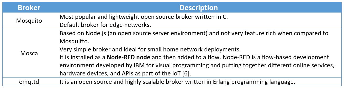
There are two main options to host an MQTT broker. The MQTT broker can be hosted on a locally installed or a cloud-based server. In the former, MQTT broker is installed on one’s server hardware. Depending on the requirements of each broker, one can choose from many free and open source MQTT brokers. Table4.2 below shows some of these available brokers.
Table4.2. Locally installed brokers
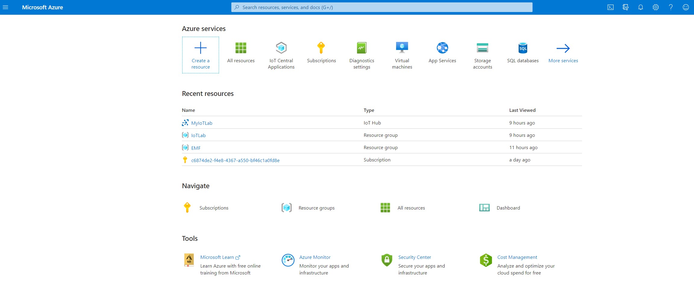
Many companies such as Google, Amazon, Microsoft, and IBM provide cloud-based MQTT server/brokers. For example, Google Cloud IoT Core provides the MQTT protocol through running a managed broker linking to the port “mqtt.googleapis.com:8883”. Note that Port 8883 is the standard TCP port reserved secure MQTT connections.
In MQTT, the broker is the central point of communication between all devices, which raises concern about having a single source of failure. To increase the reliability of the communication, most broker software and clients support automatic handover to a backup/redundant broker if the primary server fails. The software can also be set up to share the load of clients across multiple servers on cite, in the cloud, or a combination of both.
In MQTT, the network load is reduced by having the client send data only when there is a change in the values. The broker retains the published messages and sends them out to new subscribing clients. The MQTT brokers can be aware of the state of their clients and communicate that state to other clients using birth and death certificates and the Last Will and Testament (LWT) feature. MQTT clients can register an LWT message that will be sent by the broker if they suddenly disconnect. These messages can be used to let the subscribers know when a device disconnects. When a publishing client connects to a broker, it issues a birth certificate along with its LWT payload to the broker. The broker will notify any subscribing client to the same topic as the publishing client whenever the publishing client is offline or online. To ensure that the stale data is not delivered to the subscribing client if the publishing client is offline, the broker provides the subscribing client with the LWT payload. This is accomplished using a pre-configured ‘keep alive timer’ or ‘heart beat check’ between broker and publishing clients. As a result, the subscribing clients are always aware whether the publishing client is online, or when the client went offline, and what was the last known value.
The Constrained Application Protocol (CoAP) is an application-layer protocol developed by the Internet Engineering Task Force (IETF) as an extremely lightweight communications protocol stack suitable for resource-constrained devices. CoAP can be implemented over User Datagram Protocol (UDP) and is designed for devices with limited capacity to connect in Light-Weight Machine-to-Machine (LWM2M) communication. LWM2M enables remote management and control of IoT devices using a streamlined managed objects model and provides interfaces for securely monitoring and administering devices. CoAP uses the GET, PUT, POST, and DELETE methods and response codes similar to, but not exactly like, HTTP. Therefore, it is easy to map CoAP traffic from devices to the Representational State Transfer-ful (RESTful) Application Program Interface (API) logic. A RESTful API is an API that utilizes HTTP requests to GET, PUT, POST and DELETE data. An API for a website is a code that allows two software programs to exchange information between them.
CoAP uses the resource model mapped to the Universal Resource Identifier (URI) instead of MQTT topics. However, there is a similarity between the CoAP URIs and MQTT topics. For example, sensor devices publishing their sensor information to a server could be described in the following manner:
CoAP sensor publishing to a CoAP server
URI: coap://devices/sensors/temperature
MQTT client publishing to a sensor queue on the broker
topic: “/devices/sensors/temperature”
In simple terms, the operation of CoAP can be summarized as follows. A UDP packet is transmitted to request data from the other end-point (a GET on a device URL). Next, a response packet including the requested information (e.g., the temperature value of a sensor) is sent back. Note that a packet of data can also be pushed to a device – a POST to its URL.
CoAP and HTTP protocols have many similar features with the difference that CoAP is optimized for IoT and more specifically for M2M. CoAP has low overhead and is very simple to parse. It has proxy and caching capabilities and exchanges messages asynchronously.
As it is shown in Figure4.3, CoAP is made of two different layers: messages layer which is the lowest layer and deals with UDP, and request/response layer which manages request/response interactions.
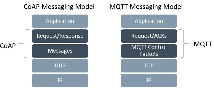
The messages layer sits on top of the UDP and deals with exchanging messages between the IoT devices and the Internet. The message duplicates are detected using the unique IDs assigned to each message. CoAP provides its own reliability mechanism using confirmable messages and non-confirmable messages.
A confirmable message (CON) is a reliable message where the client keeps sending the message using a default timeout and a back-off mechanism between retransmissions until an acknowledge message (ACK) with the same ID is received from the server. The ACK messages can carry useful payload data and themselves do not need separate ACKs.
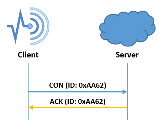
In case the server has trouble processing the CON message (e.g., when the server cannot even provide an error response), it replies with an RST message (reset message) instead of the ACK signal.
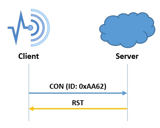
When exchanging non-critical messages, unreliable NON messages can be used where the server does not acknowledge the arrival of the messages. Although the NON messages are not acknowledged, they are assigned message IDs to detect the message duplicates.
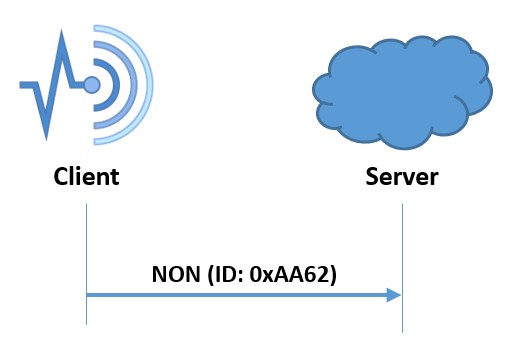
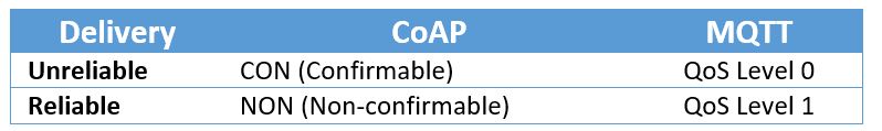
CoAP unlike MQTT does not provide an explicit QoS level model. However, the confirmable/non-confirmable message types can be mapped to the MQTT QoS semantics. Table4.3 shows CoAP and MQTT QoS mapping.
Table4.3. CoAP and MQTT QoS mapping
This layer can send the request using either a CON or NON message. In a scenario where the request is sent using a CON message, an ACK message containing the response or the error code is responded by the server provided that it can answer immediately. In such a communication scheme, the request and the response are matched using a token (this token is different than the message ID).
In case the server cannot respond right away, it sends an ACK message with no content as the response (empty response). Once the response is ready, a new CON message containing the response is transmitted to the client. After receiving the response, the client will acknowledge that. Note that the server’s response will also be a NON message, if the request sent by the client is a also a NON message.
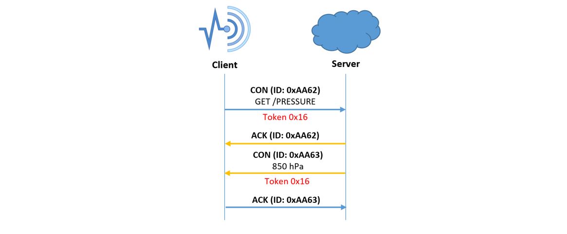
Group communications (one-to-many or multicast) which allow a single request to be sent to many devices are supported by CoAP.
Observers reduce the need for constant polling by allowing a client to receive updates based on the state of the subject. In other words, the state of a smart object is dependent on the states of the other devices that it is connected to. An example of observers in action is when a motor reacts to a sensor measuring the rotational speed of a generator, by adjusting its speed accordingly. The observer client’s status keeps updating until either a CON message is unacknowledged or an explicit removal message is sent by the client, or the last notification is expired.
Same as HTTP, CoAP is also a plaintext protocol by default which means that to secure the communication, an additional encrypted protocol as a wrapper is required. In CoAP the data encryption is done by Datagram Transport Layer Security (DTLS) over UDP to secure and protect the information.
AMQP is a lightweight application layer protocol optimized for higher security and reliability, easier provisioning and interoperability. AMQP protocol supports both publish/subscribe (such as MQTT) and request/response (such as CoAP) architectures. AMQP is a connection-oriented protocol (the client and the broker need to establish a connection before they transfer data) because it uses TCP as its transport protocol. AMQP is a considered a reliable protocol with two levels of QoS for message delivery including unsettle format (similar to MQTT QoS 0) and settle format (reliable similar to MQTT QoS 1).
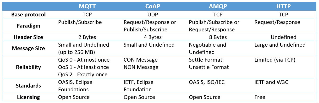
As it was seen in the previous sub-sections each IoT protocol has its own data transfer model. For example comparing the two IoT protocols we discussed earlier in this chapter, MQTT and CoAP use publish/subscribe and request/response models, respectively. In MQTT, a central broker is used to forward the received messages from the publisher to the subscribers (MQTT can support multiple publishers and subscribers for the same topic). On the other hand, similar to the HTTP, CoAP is basically a one-to-one protocol. MQTT is an event-oriented protocol (the client will publish a topic whenever there is an update) while CoAP is more suitable to transfer the state of the device. The main difference between CoAP and MQTT results from the MQTT requirement to run on the reliable, lossless, in-order, byte-stream delivery transport, which effectively mandates the TCP/IP stack. CoAP, on the other hand, runs on top of UDP and provides its own reliability mechanism using confirmable and non confirmable message types. Overall, MQTT/TCP traffic requires approximately 10x more transactions and the data overhead is approximately 100x higher compared to the CoAP/UDP traffic for the 5-byte payload. The characteristics of the IoT protocols have been summarized in Table 4.4 [7].
Table4.4. Characteristics of the IoT protocols
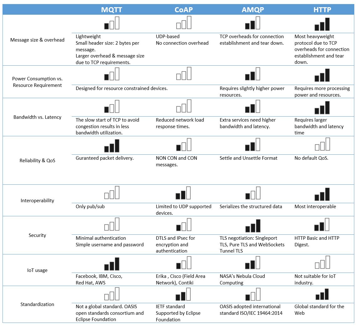
Depending on the messaging requirements of IoT use cases, different messaging protocols may be selected. This is why it is important to understand the strength and limitations of each protocol to determine their best-fit applications. Table4.5 presents an evaluation and relative analysis of the four widely accepted and used IoT protocols discussed in this chapter. This relative comparison in terms of message size, power consumption, bandwidth, reliability, security, and interoperability and so on, helps to gain insight into the pros and cons of each protocol [7].
When thinking about selecting MQTT and CoAP the following recommendations shall be taken into account:
Table4.5. IoT application protocols: comparative analysis
In this chapter, we would like a BG96 board to act as a MQTT client and publish its data with a specific topic to a broker. To build a broker, we use an architecture similar to the one used in Chapter 3. The broker is built on a computer by using Node-RED programming tool to wire together hardware devices, and online services to establish a communication with the BG96 module through MQTT protocol.
The data published on the broker will be sent to all the MQTT clients that have subscribed to the topic. To have another MQTT client, we use a MQTT client software on the same computer. The configuration used in this lab is shown in Figure 5.1. The MQTT client on the computer also can publish a message to MQTT broker that can be forwarded to BG96 board.
In Project A of this lab, we try to build the MQTT-broker and a MQTT client on a computer. In project B, we set up the BG96 board to become a MQTT client and publish the data. Since the computer is behind a NAT router and uses internal IP address, the router needs to have been setup properly and we should do port forwarding for Port 1880 and 1883.
npm install -g –unsafe-perm node-red
Table5.1. Node description and settings:1
In Lab 2, you learned how to obtain the public IP address of your computer (e.g., 172.218.32.19). Also, as it was shown in Table5.1, the MQTT port was set as 1883 (TCP/IP port 1883 is reserved with Internet Assigned Numbers Authority (IANA) for MQTT) and the topic was chosen as “sensor”, i.e., any device that subscribes to this topic will receive the messages published with this topic. If you refer to BG96 MQTT Application Note, you can find the AT Commands to publish/subscribe to a specific topic.
AT QMTOPEN=0,” 172.218.32.19 “,1883 // Open a network for MQTT client. Use your own IP OK
QMTOPEN: 0,0 //Opened the MQTT client network successfully AT QMTCONN=0,“MyClientID” // Connect a client to MQTT server. Use any client ID OK
QMTCONN: 0,0,0 AT QMTPUB=0,0,0,0,“sensor” // Publish a message to topic “sensor” >Hello MQTT. This is my message to publish. // Press CTR Z to send OK
QMTPUB: 0,0,0 |
AT QMTSUB=0,1,“sensor”,2 OK
QMTSUB: 0,1,0,1 QMTRECV: 0,2,”sensor”,”1583885887680″ // This shows the received timestamp
AT QMTDISC=0
QMTDISC: 0,0
|
Table5.2. Node description and settings:1
The flow looks like the one depicted in Figure5.4.
Microsoft Azure IoT Hub is a cloud-based managed service acting as a central message hub for two-way secure communication between the IoT application and the IoT devices that it manages. IoT Hub supports several messaging patterns such as file upload from devices, device-to-cloud telemetry, and request-reply methods to control the IoT devices from the cloud. IoT Hub monitoring helps to maintain the health of the IoT solution by tracking events such as device failures, creation, and connections [8].
In this chapter, you will become familiar with Microsoft Azure IoT Hub and create an account. Then, you will register the IoT device with Microsoft Azure IoT Hub to exchange messages.
In this example and through the procedure to create an IoT hub, we created a new resource group called “IoTLab” and entered “MyIoTLab” as the IoT hub name. In the “size and scale” tab, make sure you select the free pricing tier to avoid extra charges to your bill.
HostName=MyIoTLab.azure-devices.net; DeviceId=MyDeviceID; SharedAccessKey=W/uBNVjPNq1ntkPpv8t5xCyMyVOdy7YjrO IAVCtFi8=
Therefore, in this case:
HostName=MyIoTLab.azure-devices.net; SharedAccessKeyName=iothubowner; SharedAccessKey=8JUL6zD9joqYCQyeBIP9uyhQh6u 8BhjP/mg3u ucRg=
As you could see, the HostName is the same as for the device in the previous step; but, we have:
The Device Explorer tool is a Windows graphical tool to manage the devices in IoT Hub.
npm install -g –unsafe-perm node-red
msg.payload={
‘deviceId’:”xxxxxxxxxx”,
‘key’:”xxxxxxxxxxxx”,
‘protocol’:”mqtt”,
‘data’:msg.payload
}
return msg;
For more information on JavaScript Object Notation (JSON), visit: https://www.w3schools.com/js/js_json_intro.asp
Table6.1. Nodes settings
This part of the lab is similar to Lab 3.
AT QMTOPEN=0,” 172.218.32.19 “,1883 // Open a network for MQTT client. Use your own IP OK
QMTOPEN: 0,0 //Opened the MQTT client network successfully AT QMTCONN=0,“MyClientID” // Connect a client to MQTT server. Use any client ID OK
QMTCONN: 0,0,0 AT QMTPUB=0,0,0,0,“sensor” // Publish a message to topic “sensor” >Temp=25 // Press CTR Z to send OK
QMTPUB: 0,0,0
|
Figure6.11 shows how the received data will be represented in Device Explorer tool.
By conducting this lab you were able to communicate with Microsoft Azure IoT Hub. Now, if you are interested, you can make yourself familiar with other features of Microsoft Azure to create a dashboard and visualize the data, store the data on the cloud or send email alerts.
APN Access Point Name
ACK Acknowledgement
AMQP Advanced Message Queuing Protocol
AWS Amazon Web Services
API Application Program Interface
BER Bit Error Rate
CIoT Cellular IoT
CON Confirmable
CoAP Constrained Application Protocol
DTLS Datagram Transport Layer Security
DL Downlink
EEG Electroencephalogram
ERP Enterprise Resource Planning
eDRX Extended Discontinuous Reception
GNSS Global Navigation Satellite System
HTPP HyperText Transfer Protocol
IM Instant Messaging
ICCID Integrated Circuit Card Identifier
IMEI International Mobile Equipment Identity
IANA Internet Assigned Numbers Authority
IETF Internet Engineering Task Force
IoT Internet of Things
IP Internet Protocol
JSON JavaScript Object Notation
LWT Last Will and Testament
LWM2M Light-Weight Machine-to-Machine
LPWA Low Power Wide Area
MQTT Message Queue Telemetry Transport
NB-IoT Narrow Band Internet of Things
NAT Network Address Translation
NON Non-confirmable
PDP Packet Data Protocol
PSM Power Saving Mode
QoS Quality of Service
RAT Radio Access Technologies
RSSI received signal strength indicator
SSL Secure Socket Layer
TCP Transport Control Protocol
TLS Transport Layer Security
URI Universal Resource Identifier
UL Uplink
UDP User Datagram Protocol
UE User Equipment
[1] IoT Analytics, “IoT Platforms: The central backbone for the Internet of Things,” 2015.
[2] R. Barton, G. Salgueiro, J. Henry, D. Hanes, P. Grossetete, “IoT Fundamentals: Networking Technologies, Protocols, and Use Cases for the Internet of Things,” 1st Edition, Cisco Press, 2017.
[3] F. John Dian, and Reza Vahidnia, “IoT Use Cases & Technologies,” ISBN978-1-990132-00-1, 2020.
[4] F. J. Dian and R. Vahidnia, “LTE IoT Technology Enhancements and Case Studies,” IEEE Consumer Electronics Magazine, vol. 9, no. 6, pp. 49-56, Nov 2020.
[5] N. Naik, “Choice of effective messaging protocols for IoT systems: MQTT, CoAP, AMQP and HTTP,” IEEE International Systems Engineering Symposium (ISSE), pp. 1-7, 2017.
[6] [Online]. Available: nodered.org.
[7] N. Naik, “Choice of effective messaging protocols for IoT systems: MQTT, CoAP, AMQP and HTTP,” in IEEE International Systems Engineering Symposium (ISSE), Vienna, 2017 .
[8] [Online]. Available: https://docs.microsoft.com/en-us/azure/iot-hub/about-iot-hub.
[9] “Cellular and LPWA IoT Device Ecosystems, IoT Research Series,” 2018.
[10] “Leading the LTE IoT evolution to connect the massive Internet of Things,” Qualcomm, 2018.