Trigonometry and Single Phase AC Generation for Electricians

Trigonometry and Single Phase AC Generation for Electricians

Chad Flinn

BCIT

Vancouver, BC

Contents

1

About Trigonometry and Single Phase Generation for Electricians

Trigonometry and Single Phase Generation for Electricians was funded, in part, by an OER Grant provided by BCcampus Open Education.

BCcampus Open Education began in 2012 as the B.C. Open Textbook Project with the goal of making post-secondary education in British Columbia more accessible by reducing students’ costs through the use of open textbooks and other OER. BCcampus supports the post-secondary institutions of British Columbia as they adapt and evolve their teaching and learning practices to enable powerful learning opportunities for the students of B.C. BCcampus Open Education is funded by the British Columbia Ministry of Advanced Education, Skills & Training, and the Hewlett Foundation.

Open educational resources (OER), including open textbooks, are teaching, learning, and research resources that, through permissions granted by the copyright holder, allow others to use, distribute, keep, or make changes to them.

This textbook has been copy edited based on this style sheet [Word File].

Instructors using this book in the classroom are asked to fill out the Adoption of an Open Textbook form.

I

Trigonometry

To have a good grasp of electrical theory it is important to have a grasp of trigonometry.  Whether we are talking about single phase or polyphase power, trigonometry is a key concept.  The first part of this textbook will look at one of the most basic parts of trigonometry: the triangle.

Learning Objectives

  • Define different types of angles
  • Identify the attributes of right triangles
  • Apply Pythagoras’ theorem
  • Demonstrate trigonometry using right triangles
  • Explain impedance triangles
  • Explain power triangles
See the Trigonometry section of the Appendix for worksheets that can be used in this section.

1

Angles

What’s the deal with angles anyway?

Before we even get into trigonometry, we need to discuss angles.  Don’t worry.  Things are not going to get too crazy.  I promise.

Let’s go over the basics first.

Degree.  One-three-hundred-and-sixtieth of the circumference of a circle.  It is also the unit by which we measure angles.


Figure 1. Degrees

Angle.  This is the space between two intersecting lines.


Figure 2. Angle

Complementary angles.  These are two angles whose sum equals 90 degrees.


Figure 3. Complementary angle

Supplementary angles.  These are two angles whose sum equals 180 degrees.


Figure 4. Supplementary angle

Acute angle.  An angle that is less than 90 degrees.


Figure 5. Acute angle

Obtuse angle.  An angle that is greater than 90 degrees.


Figure 6. Obtuse angle

Similar angles.  It is possible for triangles to each have different sized sides but share the same sized angles.  These are called similar angles.


Figure 7. Similar angles

Right angle.  This is an angle that is 90 degrees.


Figure 8. Right angle

There is a ton of information about angles that we don’t need to get into.  Remember:  Try not to overcomplicate things.  Just focus on the basics and you’ll be fine.

Next up:  Triangles

2

Triangles

Why triangles are important

Learning about electrical theory necessitates the study of triangles.  More specifically: right triangles.  Before we dig too much into the right triangle, let’s go over two key points about triangles.

Figure 9. Triangle

Different triangles

The right triangle is the most common triangle that will be used in electrical theory.  It is a good idea to have a basic understanding of other triangles as well.  Here are some common triangles you will come across in trigonometry.

Isosceles triangle.  This triangle has two sides that are equal, and two angles that are equal.


Figure 10. Isosceles triangle

Equilateral triangle.  All three sides of this triangle are equal, and all three of its angles are equal too.


Figure 11. Equilateral triangle

Similar triangles.  These triangles each have different sized sides, but they share the same sized angles.

Figure 12. Similar triangles

So what about these right triangles you were talking about?

A right triangle is a triangle that has one right angle (equal to 90 degrees).  This means that the other two angles are complementary, that is, they must add to 90 degrees.

Figure 13. Complementary angles.

Ok, so what does a right triangle have to do with electrical?

Quite a bit actually.

In the world of electrical theory, we will have to add up values.  We call these units vectors (more on the concept of vectors in a later chapter). These vectors each head in a different direction.  In fact, they are 90 degrees to each other.  When we add them, the sum of these two vectors ends up being the point between the two sides.


Figure 14. Vector triangle

Because they are not heading in the same direction (they are heading in directions that are 90 degrees to each other) we can’t add them up normally.  They have to be added vectorially.  How do you do this?  I’m glad you asked.

Up next:  Pythagoras’ theorem

3

Pythagoras

Who is this Pythagoras and why does he matter?

Pythagoras was a Greek philosopher who lived around 500 BC.  He is credited as being a philosopher and mathematician.  Much of what we know of Pythagoras is from writings that were copied down hundreds of years after his death, so the validity of what we do know is questionable.  He is credited with Pythagoras’ theorem when actually it has been proven that Babylonians and Indians were using variations of it for hundreds of years before he even came along. You can read more about Pythagoras in this article.

Thanks for the history lesson, but get on with it!

The Pythagorean theorem, also known as Pythagoras’ theorem, is a relation in Euclidean geometry among the three sides of a right triangle.  ‘It states that the square of the hypotenuse (the side opposite the right angle) is equal to the sum of the squares of the other two sides.

Huh?

It’s not as bad as it seems.  Basically, the Pythagoras’ theorem says that you can figure out any side of a right triangle as long as you have the other two sides, using the equation:

Important Formula!

A+ B= C2

When we look at the formula, there is one important thing to remember:  C is always the longest side.

A and B can be swapped around, but when using this formula, C is always the longest side (which is also the side opposite the 90-degree angle).

Figure 15. Longest side triangle


Video!

This video walks through how to apply Pythagoras’ theorem on a right triangle.

Thumbnail for the embedded element "Pythagoras theory"

A YouTube element has been excluded from this version of the text. You can view it online here: https://pressbooks.bccampus.ca/trigforelectricians/?p=24

Attributions

Pythagoras Theory. video by The Electric Academy is under a Creative Commons Attribution Licence.

4

Naming Right Triangle Sides

What is this big fancy word, trigonometry?

Trigonometry is the study of the relationship that exists between the sides and the angles of a triangle.

That sounds complicated and scary.

It can be, but lucky for us we are only dealing with right triangles.  This makes it very simple and almost fun.  (Nerd alert!)

First steps

We have already learned how to determine the sides of a triangle using the Pythagoras’ theorem.  Next up is using those sides to determine the angles.  Lucky for us we know that in a right triangle we already have one 90-degree angle.  We also know that if we can solve any of the other two angles, the third one is easy.  (All triangles have 180 degrees.)  Our next step is to name the sides of the triangle.  The names of these sides are dependent on something called the designate angle or theta.  Theta is an angle that you determine or is determined for you.

Figure 16. Theta 1


Figure 17. Theta 2

Now once you have figured out which angle is your theta, we can get to business naming the sides.

Adjacent.  This is the side that sits adjacent to the designate angle.

Opposite.  This is the side that sits opposite to the designate angle.

Hypotenuse.  This is the side that sits opposite the 90-degree angle.

The hypotenuse is always the longest side of the triangle and doesn’t care where the designate angle is.  It only cares that it is opposite the 90-degree angle.

Figure 18. Hypotenuse

And if we switch the designate angle, the names of the sides change as in Figure 19.


Figure 19. Adjacent and Opposite sides switch places

The next chapter tells us what to do with these names.

5

Trigonometry Functions

When determining the designate angle we can use different ratios of sides.

Each ratio has a trigonometric function that helps turn the ratio into an angle.  They are:

One way of remembering the ratios are these mnemonics:

By the way,

Video!

This video walks through how to determine the angle of a right triangle when you have two sides.

Thumbnail for the embedded element "Trigonometry (Part one)"

A YouTube element has been excluded from this version of the text. You can view it online here: https://pressbooks.bccampus.ca/trigforelectricians/?p=34


Video!

This video walks through how to determine the other sides of a triangle when you have an angle and one side.

Thumbnail for the embedded element "Trigonometry (Part two)"

A YouTube element has been excluded from this version of the text. You can view it online here: https://pressbooks.bccampus.ca/trigforelectricians/?p=34

Attributions

Trigonometry (Part one).video by The Electric Academy is under a Creative Commons Attribution Licence.

Trigonometry (Part two).video by The Electric Academy is under a Creative Commons Attribution Licence.


6

Power and Impedance Triangles

What is going on here?

This is the point where I am going to ask you to take my hand and to trust me.  Okay, you don’t have to take my hand, but you do have to trust me.  We are going to start using some terms before totally going into the theory behind them.  I promise that we will get more in-depth into these concepts in future lessons.

Impedance triangles

When dealing with DC circuits the only thing that opposes current is the resistance in the circuit.

Figure 20. DC resistive circuit

As we will learn in later units, AC adds a component that opposes current as well.  This is called reactance and it runs 90 degrees to the circuit resistance.  This means it is not possible to add them together arithmetically;  it has to be done using the Pythagoras’ theorem.  When you add these two together, you get a total opposition to current flow called impedance.

Figure 21. DC inductive circuit

The triangle that is created when adding the resistance to the reactance is known as an impedance triangle.

Figure 22. Impedance triangle

In an impedance triangle, the resistance (r) is always on the bottom of the triangle, the reactance (x) always goes on the side and the hypotenuse is always the impedance (z).

Power triangles

When dealing with a purely resistive circuit, the power being dissipated is in the form of heat or light and is measured in watts and is known as true or active power.  It is a product of I2R.

Figure 23. Resistive power circuit

In an AC circuit with inductance, watts are still present.  There is also a reactive power present as current passes across the reactance.  This power is called reactive power and is also called wattless or quadrature power.  Its unit is the Vars.


Figure 24. Inductive power circuit

Much like the impedance triangle, we can not just add the two powers together to get overall power.  They must be added using the Pythagoras’ theorem.  Their sum is equal to the apparent power (VA).

Figure 25.  Power triangle

When calculating for reactive power, we are still able to use the power formulas.  We just have to use them with reactance instead of resistance.

Remember

When building an impedance or power triangle, the resistive component always goes on the bottom of the triangle and the reactive component always goes on the side.


II

Vectors

Vectors are something that contains magnitude and direction.  This is a concept that will continue to follow you throughout your electrical training.

Learning Objectives

  • Explain vectors
  • Describe a quadrant system
  • Discuss the difference between polar form and rectangular form
  • Demonstrate how to add vectors
See the Vectors section of the Appendix for worksheets that can be used in this section.

7

A Vector Primer

What is a vector?

A vector is a quantity that possesses magnitude and direction.  As an example, let’s say I roundhouse kicked you in the head.  The magnitude of the force and the angle at which I kicked you would be a vector.  I know what you’re thinking:  “This electrical stuff sounds cool.”  And you’d be right.


Image retrieved from pixabay.com. Used under Creative Commons CC0 license.

Aside from helping me become a fighting machine, how do vectors have anything to do with electricity?

AC values are constantly changing magnitude and direction.  We will talk about this more in-depth in the AC generation portion of the course.  Eventually, we will be required to add these values together.  The sum of the vectors is called the resultant.  This is all well and good when vectors are heading in the same direction…


Figure 26. Vectors in the same direction

… because you can just add them together.


Figure 27. Vectors in the opposite direction

It isn’t even bad if they are heading in the opposite direction.  You can just subtract them.  The only thing when adding them in opposite directions is that you have to pay attention to which vector has the greatest value.  This will become the new direction of the sum of the vectors.

The problem arises when they are heading in completely different directions.


Figure 28. Vectors moving in different direction

How did you do that?

Trust me, it is not difficult.  In order to figure out how to add vectors, we first have to talk about the quadrant system.

Up next:  Quadrants

8

Quadrants

Like a Star Trek quadrant?

First off: Nerd alert!

Secondly,  yes,  a quadrant is a circle cut into four parts.

What does this have to do with electricity?

Voltage and currents are constantly changing magnitude and direction.  When changing direction, they actually rotate in a counterclockwise direction.  They are tethered to a point of origin.


Figure 29. Quadrant point of origin

Each quadrant contains certain directions.

This is very important as it helps us to determine which vectors belong in which quadrant.

Polarity

It is also important to understand polarity when dealing with quadrants.  A quadrant system is basically an X-Y graph.  We use the point of origin as a reference point.  On the X axis, anything to the right of the point of origin is positive and anything to the left is negative.  On the Y axis, anything above the point of origin is positive and anything underneath it is negative.  This means each quadrant has its own polarity, as shown in Figure 30.


Figure 30. Quadrant polarity

This too is extremely important when it comes to adding vectors.

Are you getting excited yet?  This is all going to come together in one magical dance.

Video!

This video goes into greater detail about the specifics of all four quadrants.

Thumbnail for the embedded element "Quadrants and vectors"

A YouTube element has been excluded from this version of the text. You can view it online here: https://pressbooks.bccampus.ca/trigforelectricians/?p=65

Attributions

Quadrants and vectors. video by The Electric Academy is under a Creative Commons Attribution Licence.

9

Polar vs. Rectangular Form

Polar form

When dealing with vectors, there are two ways of expressing them.  Up to this point, we have used a magnitude and a direction such as 30 V @ 67°.  This is what is known as the polar form.  It is more often the form that we like to express vectors in.

Rectangular form

Rectangular form breaks a vector down into X and Y coordinates.  In the example below, we have a vector that, when expressed as polar, is 50 V @ 55 degrees.  The first step to finding this expression is using the 50 V as the hypotenuse and the direction as the angle.  Next, we draw a line straight down from the arrowhead to the X axis.  What does this look like to you? If you said right triangle, give yourself a pat on the back.  We then can use the angle and the hypotenuse to determine the X axis with these equations:

This is accomplished just by transposing the ratios from what we learned previously in trigonometry.


Figure 31. Quadrant 1


We then can express the same vector as 28.7,  j 41.

Where did that j come from?

The letter j is put in front of the y component to indicate the difference between the X and the Y.  The reason j is used is this.

As a way of telling the difference between X and Y, it was decided that a letter should be put in front of the Y.  The X and Y components don’t really exist, and are referred to as imaginary numbers.  Because each is an imaginary number, the letter i was suggested.  However, the letter i is also used as a symbol for current, so it was decided to go with the letter j instead.

Why polarity is important

Let’s look at another example.  The polar form is 60 V @ 140 degrees.  This puts the vector in the second quadrant.

In the second quadrant, X is – (negative) and Y is + (positive).  The angle of 140 degrees is used from the 0-degree point.  To use trigonometry, we need to determine what the angle is in reference to the X axis.  In this example, it is 40 degrees (the supplement of 140 degrees).  After that, we can use trigonometry to determine the X and Y components.


Figure 32. Quadrant 2

If we are going to express it in rectangular form, use -46, j39.  Remember that the X component is negative and the Y component is positive as they are in the second quadrant.

Video!

This video walks through how to convert from polar form to rectangular form.

Thumbnail for the embedded element "Converting Polar to Rectangular"

A YouTube element has been excluded from this version of the text. You can view it online here: https://pressbooks.bccampus.ca/trigforelectricians/?p=68

Rectangular to polar

Up to this point, we have been converting the polar form to rectangular.  It is possible–and even important–to convert from rectangular to the polar form.  If you have been given the rectangular coordinates, the best thing you can do is chart them out.

For instance, if you are given the coordinates 50, j80, then:

Step 1.  Draw them out on an X-Y chart.


Figure 33. Quadrant X and Y (step 1)

Step 2.  Draw in the resultant and use Pythagoras’ theorem to determine its size.

Figure 34. Quadrant X and Y (step 2)

Step 3.  Use trigonometry to determine the angle.


Figure 35. Quadrant resultant (step 3)

Step 4.  Using the resultant and the angle, go ahead and express it in polar form:  94 @ 58°

Congrats, you did it!

Video!

This video walks through how to convert from rectangular form to polar form.

Thumbnail for the embedded element "Converting from Rectangular to Polar form"

A YouTube element has been excluded from this version of the text. You can view it online here: https://pressbooks.bccampus.ca/trigforelectricians/?p=68

Heed the quadrant!

There is one thing you need to watch.  You need to be aware of what quadrant you are in.  This is especially important when dealing with the direction (angle).  When we work out the angle using the Pythagoras’ theorem, we use the angle in relation to the X axis but not the direction of the vector.  Confused?  Look at the example below where the coordinates -36,  j29 are given.


Figure 36. Quadrant 2 angle

Using Pythagoras and trigonometry, we worked out that the resultant was 46 and the angle, in reference to the X axis, was 38.4 degrees.  However, the polar form would not be 46 @ 38.4 degrees.  We have to take into account that it is in the second quadrant.  That means the direction must be somewhere between 90 and 180 degrees.  In order to work out the actual direction in this example, we take 180 degrees and subtract 38.4 degrees from it to get 141.6 degrees.


Figure 37. Quadrant 2 resultant angle

In the third quadrant, we calculate the angle in reference to the X axis and add 180 degrees to it.  In the fourth quadrant, we calculate the angle and subtract it from 360 degrees.

Something cool about the fourth quadrant

When we are dealing with the fourth quadrant, there are two ways we can express the direction.  We can work out the angle relative to the X axis and subtract it from 360 degrees as previously stated.  Or, another way to express it is to work out the angle and then throw a negative sign in front of it.  Mathematically it is the same thing.  In this example, it can be expressed as 80 V @ 340° or 80 V @ −20°.


Figure 38. Quadrant 4 angle

Didn’t someone mention something about adding vectors?

Attributions

Converting Polar to Rectangular. video by The Electric Academy is under a Creative Commons Attribution Licence.

Converting Rectangular to Polar form. video by The Electric Academy is under a Creative Commons Attribution Licence.

10

Vector Addition

A quick recap

There was a fair bit to wrap our heads around before we finally got into vector addition.

Here are some of the key points:

Okay, let’s learn how to add vectors.

Adding vectors

When adding vectors, we have to find some common ground.  This is why we focus on the X and Y coordinates.  Each vector can be broken down into X and Y coordinates.  This allows us to find some common ground as the X coordinates are heading in the same direction and the Y coordinates are heading in the same direction.  Let’s look at the example in Figure 39.

In this example, we have one vector that is 38 V @ 20 degrees and another that is 100 V @ 135 degrees.

Figure 39. Adding vectors 


The first step is to draw in the X and Y axes. (See Figure 40.)  This will help provide us with a reference when determining our X and Y coordinates.


Figure 40. Adding vectors draw quadrant

Next we will work out the X and the Y for each vector, in Figure 41.


Figure 41. Adding vectors determining X and Y

Next add an X-Y chart and enter the coordinates (Figure 42).


Figure 42. Adding vectors X and Y chart

Add up your X coordinates and your Y coordinates and you have your answer in rectangular form (Figure 43).


Figure 43. Adding vectors for rectangular form

Take your rectangular form and chart it on its own (Figure 44).


Figure 44. Adding vectors for polar form

Take the resultant and the angle, and convert it to polar form:  90.6 @ (180°−68°)90.6 @ 112°.

There you have it.  If you have more vectors, you just keep adding other rows to your X-Y chart.

Video!

This video walks through how to add vectors heading in completely different directions.

Thumbnail for the embedded element "Vector addition"

A YouTube element has been excluded from this version of the text. You can view it online here: https://pressbooks.bccampus.ca/trigforelectricians/?p=71

Attributions

Vector addition. video by The Electric Academy is under a Creative Commons Attribution Licence.


III

AC Generation

Where does voltage come from?  How do we get it?  Thanks to people such as Michael Faraday and Joseph Henry we now have an idea how to harness the energy that was once attributed to the gods.

Learning Objectives

  • Explain electromagnetic induction
  • Describe the difference between a simple alternator and practical alternator
  • Discuss how a waveform is generated
  • Analyze a waveform and determine how effective, instantaneous, and average values are calculated
See the AC Generation section of the Appendix for worksheets that can be used in this section.

11

Electromagnetic Induction

What is this electromagnetic induction of which you speak?

Electromagnetic induction is when a voltage is created by passing a conductor through a magnetic field.

Figure 45. Magnetic poles and induction

The size of the voltage can be varied by three factors:

  1. The size of the magnetic field.  The more flux lines there are, the more flux lines there are for the conductor to cut.  The strength of flux is directly proportional to the induced voltage.
  2. The active length of the conductor.  Active length meaning the part of the conductor that actually passes through the field.  The active length is directly proportional to the induced voltage.
  3. The speed at which the conductor passes through the field.  The faster the conductor passed through the field, the greater the voltage induced.  The speed is directly proportional to the induced voltage.

These relationships to voltage can be broken into this formula:  e = βlv.

Where:

e = peak voltage induced in the inductor (volts)

B = field strength between the poles (Tesla)

l = active length of conductor (meters)

v = velocity of the conductor through the field (m/sec)

Here is an example.

A conductor that has an active length of 4 meters passes through a field of 5 Tesla at a speed of 15 meters per second.  Determine the peak voltage induced on this conductor.

(4 m)(5 T)(15 m/sec) = 300 volts peak

That’s crazy!  Who discovered that?

The discovery of electromagnetic induction is attributed to Michael Faraday who discovered that when he passed a magnetic field through a conductor a current would flow.

As long as there was motion between the field and the conductor, a voltage could be induced.  This could mean the conductor passes through a field or a field passed through a conductor.

Next up:  The alternator

12

The Alternator

How do we keep the voltage coming?

We have established that if we have a conductor pass through a field or a field through a conductor a voltage is established.  This means that voltage is only established when there is constant motion.  Instead of having someone passing a conductor through a field rapidly, it was discovered that the conductor could be formed into a loop and rotated through the field to maintain a voltage.  This would be an example of what is known as a simple alternator.

A simple alternator has two magnetic poles that establish a magnetic field.  The conductor (armature) rotates through this field to establish a voltage.

Figure 46. Simple alternator


A practical alternator has a stationary conductor and the field rotates.

Figure 47. Practical alternator

 What are the parts of the alternator?

Figure 48. Simple alternator parts


Figure 49. Practical alternator parts

Armature.  This part is what the voltage is induced on to.  It can be rotating (simple alternator) or stationary (practical alternator).

Slip rings.  Made of brass, they rotate and either bring current to the load (simple alternator) or excitation to the field (practical alternator).

Brushes.  Made of graphite carbon, they are stationary and either pass current to the load (simple alternator) or current to the field (practical alternator).

Field poles.  They are either stationary (simple alternator) or rotating (practical alternator).

Prime mover.  This part spins the armature (simple) or the field (practical).  Examples include:

Which is better the simple or the practical?

If you guessed the practical, you would be right.  The brushes of a simple alternator have to be sized for the load.  If you have a large load that draws a lot of current, then your brushes would have to be sized accordingly.  Whereas, with the practical alternator the brushes bring current to the field and can be small yet still allow enough current to adjust the field.  With either alternator, the easiest way to adjust the voltage is by varying the field strength.  It is possible to vary the speed on the alternator to adjust the voltage, but this will also change the frequency.

Next up:  How an alternator creates a sine wave

13

How a Waveform Is Generated

AC generation with an alternator

If Faraday has taught us anything it is this:  Any time you pass a conductor through a magnetic field, you induce a voltage.  If we take that conductor and turn it into a loop and spin it continually through that magnetic field, we have created an alternator.

Figure 50. Alternator picture

This means that a voltage will constantly be induced.  However, this is not a flat line voltage like direct current.  It creates an oscillating voltage that rises and falls.

Is this what you mean by sine wave generation?

Yup, this is exactly what I mean.  As the conductor spins through the field, there will be times that it does not cut any lines of flux.  There will be times when it cuts some of the lines of flux, and there will be times that it is cutting the maximum amount of flux lines that it can.  This means that at some point during the sine wave generation there will be no voltage generated.  Then there will be some voltage generated, and then there will be a maximum voltage generated.  This creates this thing of beauty.  A sine wave.

Figure 51. Sine wave

Oh yeah, I think I have seen that before

This wave pattern occurs often in nature, including ocean waves, sound waves and light waves.  In fact, if you take the hours of daylight in a day and graph it out with the months of the year, guess what?  A sine wave is generated.  If you’d like to read an interesting article on the seasons and sine wave generation, read Calculus of the seasons.  Isn’t nature cool?  But I digress.  This sine wave is extremely important when it comes to electrical generation.  Future postings will discuss its importance and go into in-depth analysis of the waveform.

Video!

This video explains how a sine wave is generated in an alternator.

Thumbnail for the embedded element "Sine Wave generation"

A YouTube element has been excluded from this version of the text. You can view it online here: https://pressbooks.bccampus.ca/trigforelectricians/?p=163

Sounds like fun

Oh, it’s fun all right.  Trust me.  If you find this stuff interesting, it becomes a lot easier to learn and understand.  (Fatherly lecture over).  If you have a foundational understanding of this concept, then single phase and three-phase generation should be a snap.

Attributions

Sine wave generation. video by The Electric Academy is under a Creative Commons Attribution Licence.

14

AC Waveform Analysis

What fun can we have with that waveform?

Well, it turns out that there is an awful lot going on in that waveform.  Most of it is actually useful as well.

Video!

This video shows all that is happening in the sine wave.

Thumbnail for the embedded element "AC Waveform analysis"

A YouTube element has been excluded from this version of the text. You can view it online here: https://pressbooks.bccampus.ca/trigforelectricians/?p=165

To recap

Attributions

AC waveform analysis. video by The Electric Academy is under a Creative Commons Attribution Licence.

15

Frequency and Alternators

In the last chapter, we learned the term cycle means from the point in a waveform to where the waveform starts to repeat itself.  When we discuss the term frequency, we are referring to how many cycles can occur in one second.  Frequency is measured in hertz (shout out to Heinrich Hertz) or CPS (cycles per second).  Two factors affect the frequency in an alternator: rotation speed and the number of poles.

Figure 52. Sine wave cycle

Rotation speed

As the armature rotates through the field, it starts to create a waveform (as we saw in the last chapter).  One full mechanical rotation of the armature creates one full sine wave on a two-pole alternator.  If the two-pole alternator spins three complete revolutions in one second, it will create three full sine waves in that one second.  We would say that the frequency is at three cycles per second or three hertz (as the cool kids say).

A machine’s rotational speed is measured in rotations per minute or RPM.  However, we are not concerned with minutes, but rather, with seconds when dealing with frequency.  Therefore, RPM must be converted to rotations per second (RPS).  As there are 60 seconds in a minute, all we have to do is to divide the RPM by 60 to convert it to RPS.

For example, if the armature is spinning at a rate of 1800 RPM on a two-pole alternator, we can say that it is spinning at 30 rotations per second.  If this alternator has two poles, then in one second it will generate 30 cycles of voltage.  It then could be said to have a frequency of 30 cycles per second or 30 Hertz.  The frequency of an alternator is directly proportional to the rotational speed of the alternator.

Number of poles

If we add poles to the alternator, we can change the frequency.  In a two-pole alternator,  Side A of the armature (seen in Figure 53) passes from north to south, and then south to north, to create one complete sine wave. I f we add two more poles, as in Figure 54, then Side A of the armature will move past two north poles and two south poles in one full mechanical revolution.

Figure 53. Two pole alternator

Two full sine waves are created in one complete mechanical revolution.  If a two-pole alternator creates one cycle of voltage in one second (or one hertz of frequency), a four pole alternator will create two cycles of voltage in one second (or two hertz).

The frequency of an alternator is directly proportional to the number of poles in the alternator.

Figure 54. Four pole alternator

Formula time!

Knowing that rotation speed is directly proportional to frequency and that the number of poles is directly proportional to frequency, we can use a formula.  The formula looks like this:


Figure 55. Frequency formula

Where…

f = frequency in hertz

P = number of poles

N = rotational speed in RPM

We divide the number of poles by two because there will always be a set of two poles.  You can’t have a north pole without a south.  We divide the RPM by 60 because we are concerned with rotations per second, not rotations per minute.  The formula in Figure 56 can be combined to look like this:


Figure 56. Combined frequency formula

Video!

This video will walk you through how frequency is related to the RPM and the number of poles of an alternator.

Thumbnail for the embedded element "How RPM and number of poles affect frequency"

A YouTube element has been excluded from this version of the text. You can view it online here: https://pressbooks.bccampus.ca/trigforelectricians/?p=278

Attributions

How RPM and number of poles affect frequency. video by The Electric Academy is under a Creative Commons Attribution Licence.

1

Appendix: Worksheets

Click on the links below to download the PDF worksheets for each unit.

Trigonometry

Vectors

AC Generation

2

Glossary

active power:  The power dissipated in the form of heat or light when dealing with a purely resistive circuit.  It is also known as true power.

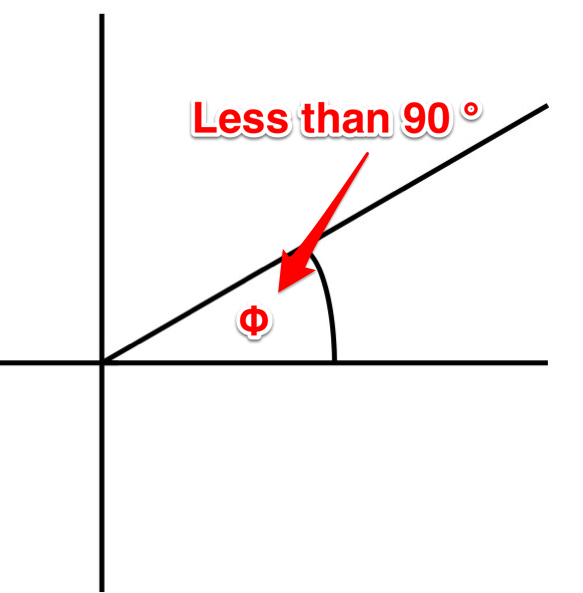
acute angle:  An angle that is less than 90 degrees.

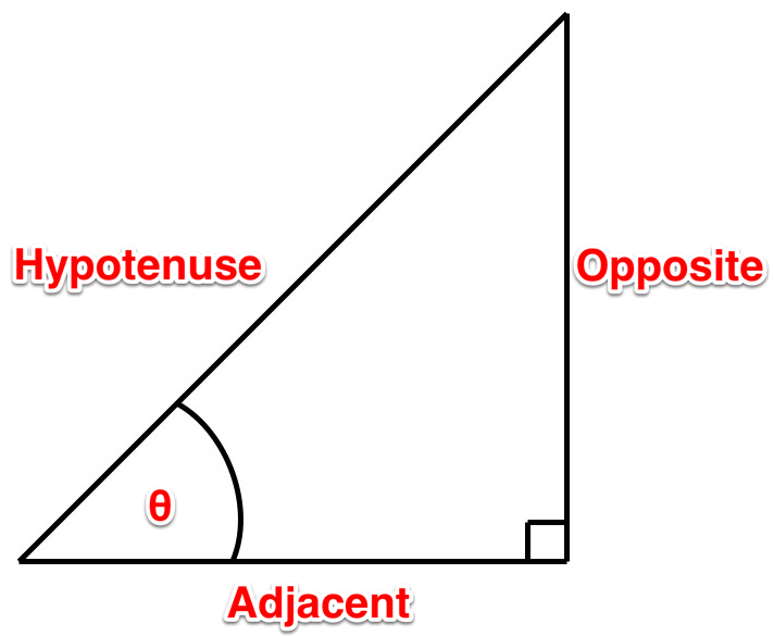
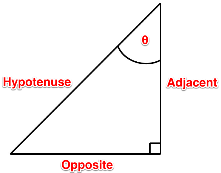
adjacent:  The side of a triangle that sits adjacent to the designate angle.

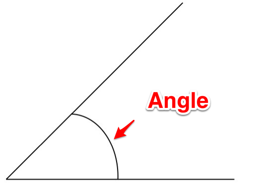
angle:  The space between two intersecting lines.

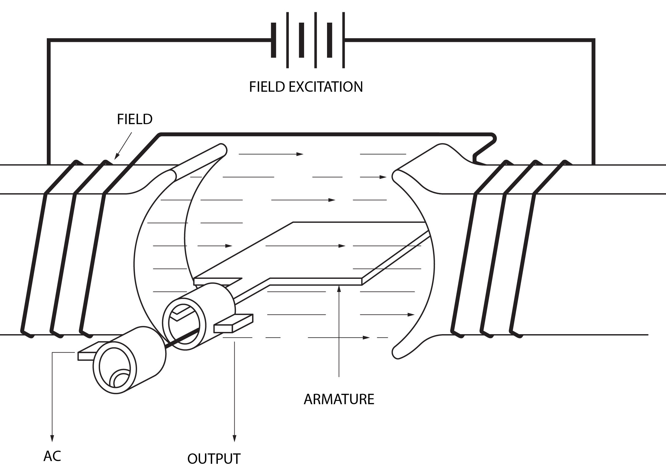
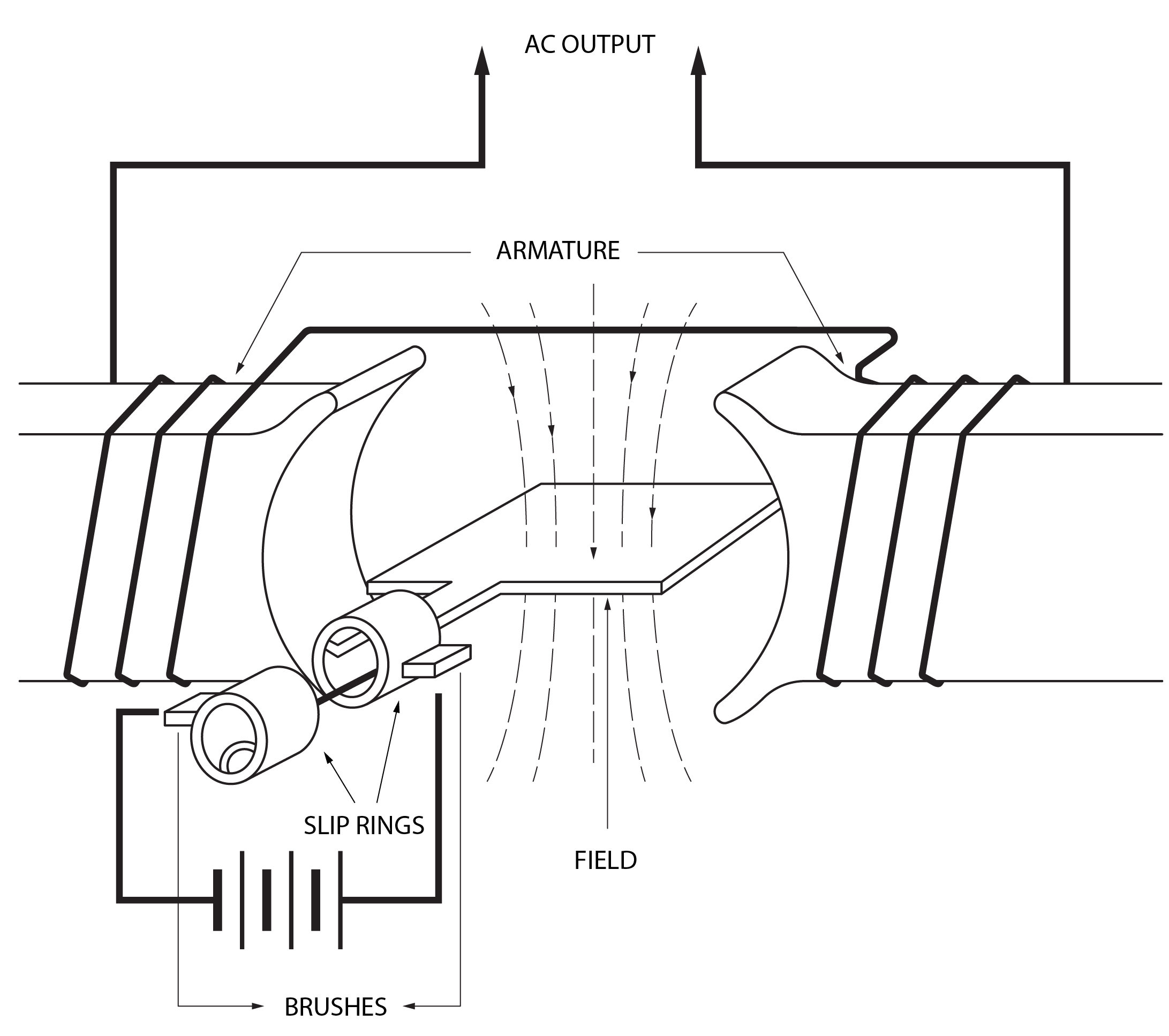
armature:  The part of an alternator where the voltage is induced on to.  It can be rotating (simple alternator) or stationary (practical alternator).

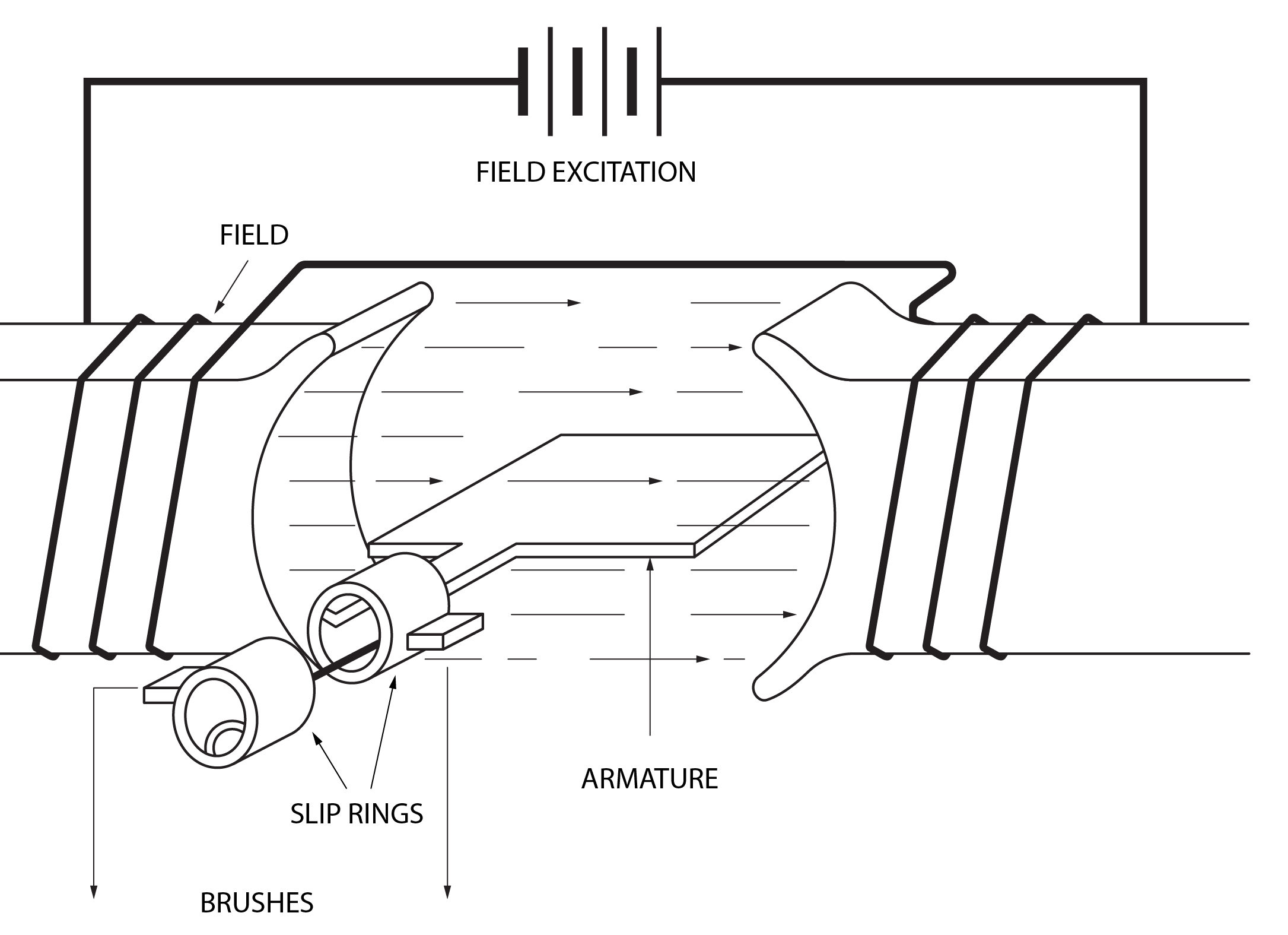
brushes:  The parts of an alternator that are made of graphite carbon.  They are stationary and either pass current to the load (simple alternator) or current to the field (practical alternator).

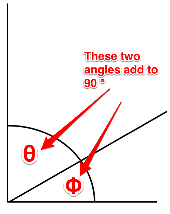
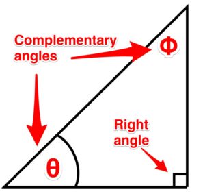
complementary angles:  Two angles whose sum equals 90 degrees.

CPS:  Short for cycles per second, used to measure frequency.

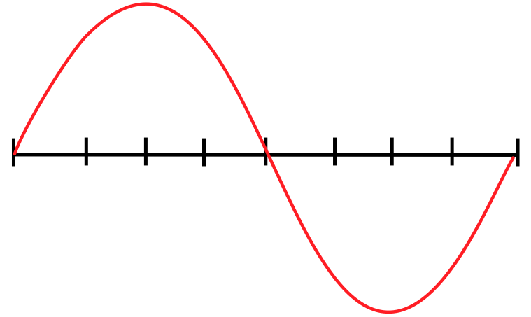
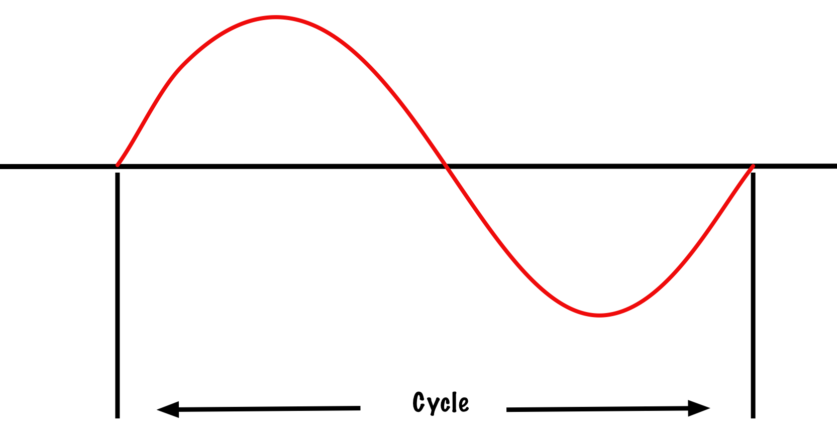
cycle:  From the point in a waveform to where the waveform starts to repeat itself.

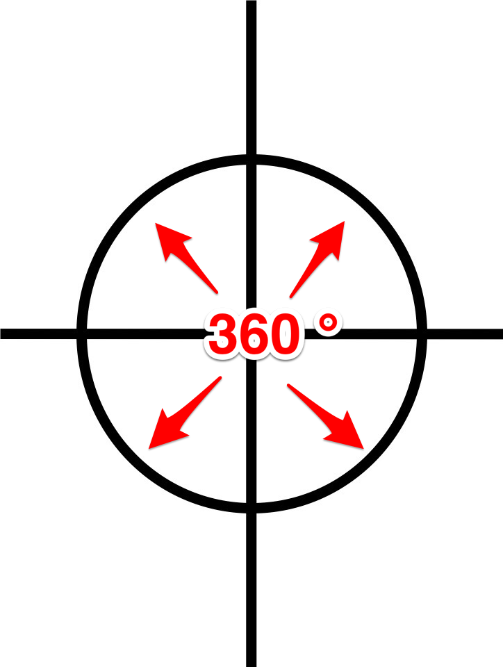
degree:  One-three-hundred-and-sixtieth of the circumference of a circle.  It is also the unit by which we measure angles.

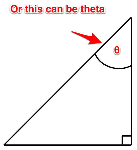
designate angle (or theta):  An angle that you determine or is determined for you, and upon which triangle sides (adjacent, hypotenuse, opposite) are named and dependent.

electromagnetic induction:  When a voltage is created by passing a conductor through a magnetic field.

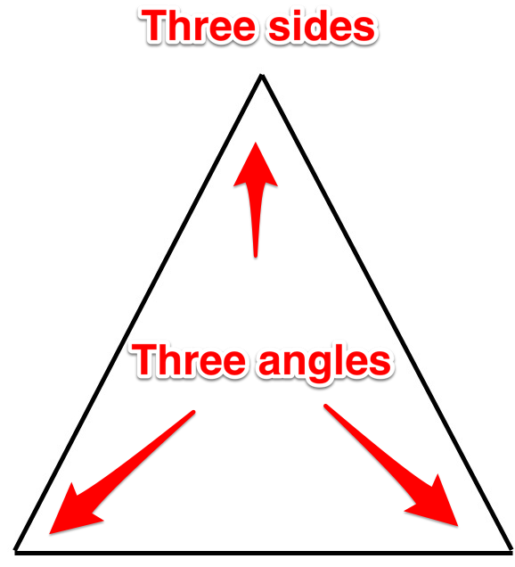
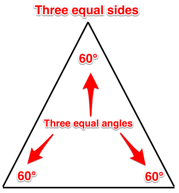
equilateral triangle:  All three sides of this triangle are equal, and all three of its angles are equal too.

field poles:  The parts of an alternator that are either stationary (simple alternator) or rotating (practical alternator).

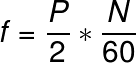
frequency:  The number of cycles can occur in one second.  Frequency is measured in hertz or CPS (cycles per second).

hertz (Hz):  The unit used us measure frequency.

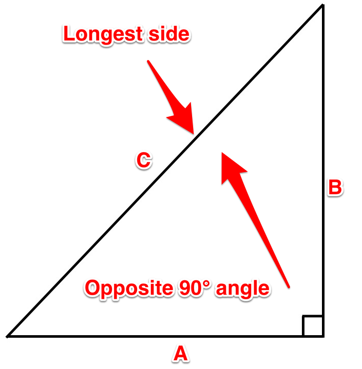
hypotenuse:  The side of a triangle that sits opposite the right, or 90-degree, angle.  It is always the longest side of the triangle.

imaginary numbers:  A term referring to components that don’t really exist such as X and Y.

impedance:  A total opposition to current flow determined by adding reactance to resistance using the Pythagoras’ theorem.

impedance triangle:  The triangle that is created when the resistance is added to the reactance.

isosceles triangle:  This triangle has two sides that are equal, and two angles that are equal.

obtuse angle:  An angle that is greater than 90 degrees.

opposite:  The side of a triangle that sits opposite to the designate angle.

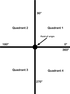
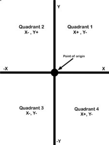
point of origin:  A reference point.

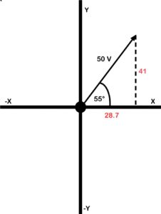
polar form:  An expression of vectors using magnitude and direction. See rectangular form.

practical alternator:  Has a stationary conductor and the field rotates in order to maintain voltage.  See simple alternator.

prime mover:  The part of an alternator that spins the armature (simple) or the field (practical).  Examples include combustion engine, hydro dam, hand crank and windmill.

Pythagorean theorem/Pythagoras’ theorem: A relation in Euclidean geometry among the three sides of a right triangle. It states that the square of the hypotenuse (the side opposite the right angle) is equal to the sum of the squares of the other two sides. In simple terms, this theorem says that you can figure out any side of a right triangle as long as you have the other two sides, using the equation:
A+ B= C2

quadrant: A circle cut into four parts.

quadrature power:  See reactive power.

reactance:  The component that opposes current in an AC circuit.  This runs 90 degrees to circuit resistance.

reactive power:  The power that is present when current passes across the reactance.  It is also known as wattless or quadrature power.

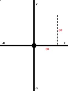
rectangular form:  An expression of vectors using X and Y coordinates. See polar form.

resistance:  The component that opposes current in a DC circuit.

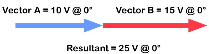
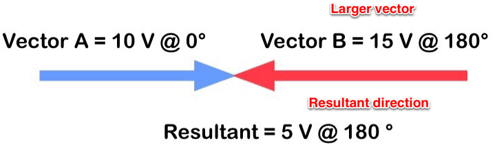
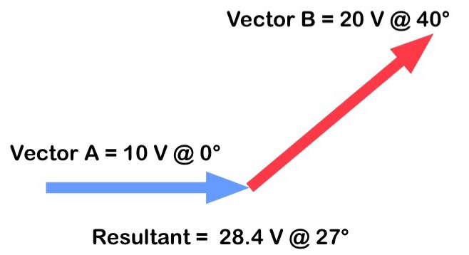
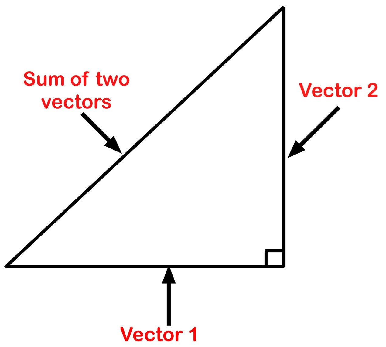
resultant:  The sum of the vectors.

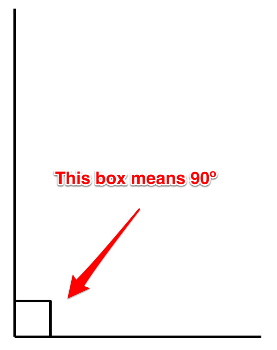
right angle:  An angle that equals 90 degrees.

RPM:  Short for rotations per minute, used to measure a machine’s rotational speed.

RPS:  Short for rotations per second.

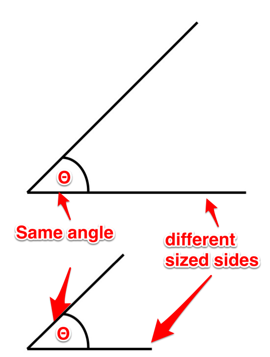
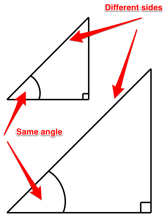
similar angles:  These triangles each have different sized sides, but share the same sized angles.  See practical  alternator.

simple alternator:  When a conductor is formed into a loop and rotates through a field to maintain voltage.

slip rings:  The parts of an alternator that are made of brass.  They rotate and either bring current to the load (simple alternator) or excitation to the field (practical alternator).

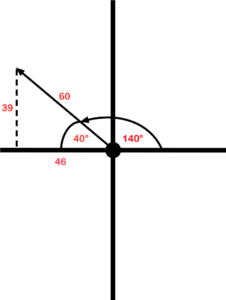
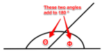
supplementary angles:  Two angles whose sum equals 180 degrees.

theta:  See designate angle.

trigonometry:  The study of the relationship that exists between the sides and the angles of a triangle.

true power:  See active power.

vector:  A quantity that possesses magnitude and direction.

vectorially:  Related to or involving vectors.

wattless power:  See reactive power.


4

Versioning History

This page provides a record of changes made to this textbook. Minor edits are acknowledged with a 0.1 increase in the version number; major edits are acknowledged with a 1.0 increase in the version number. The exported files for this book in the B.C. Open Textbook Collection reflect the most recent version.

If you find an error in this textbook, please fill out the Report an Open Textbook Error form.

Version Date Change Details
1.0 December 14, 2018 Book published in Pressbooks.
1.1 January 28, 2019 Updates made in order to publish the book in the B.C. Open Textbook Collection Added a list of links for the print copy, created a versioning history page, and added attribution information for videos.