The CC licence permits you to retain, reuse, copy, redistribute, and revise this book—in whole or in part—for free providing the author is attributed as follows:
If you redistribute all or part of this book, it is recommended the following statement be added to the copyright page so readers can access the original book at no cost:
All images in this text are by Aaron Lee and shared under a CC BY 4.0 Licence.
“Part 1: Electrical Terms and Definitions” includes chapters adapted from Basic Motor Control by Aaron Lee and Chad Flinn, which is under a CC BY 4.0 Licence. More information can be found at the end of each adapted chapter.
Sample APA-style citation (7th Edition):
Lee, A. (2021). Basic HVAC. BCcampus. https://opentextbc.ca/basichvac/
BCcampus Open Education believes that education must be available to everyone. This means supporting the creation of free, open, and accessible educational resources. We are actively committed to increasing the accessibility and usability of the textbooks we produce.
Easy navigation. This text has a linked table of contents and uses headings in each chapter to make navigation easy.
Accessible formulas. All formulas provided in this book are written in Latex and rendered with Mathjax, which makes them accessible to people using screen readers that are set up to read MathML.
Audio and text. Each chapter has an audio version of the chapter so students can listen to and/or read the content.
Accessible images. All images in this text that convey information have alternative text. Images that are decorative have empty alternative text.
Accessible links. All links use descriptive link text.
Accessibility Checklist
Element
Requirements
Pass?
Headings
Content is organized under headings and subheadings that are used sequentially.
Yes
Images
Images that convey information include alternative text descriptions. These descriptions are provided in the alt text field, in the surrounding text, or linked to as a long description.
Yes
Images
Images and text do not rely on colour to convey information.
Yes
Images
Images that are purely decorative or are already described in the surrounding text contain empty alternative text descriptions. (Descriptive text is unnecessary if the image doesn’t convey contextual content information.)
Yes
Tables
Tables include row and/or column headers that have the correct scope assigned.
Yes
Tables
Tables include a title or caption.
Yes
Tables
Tables do not have merged or split cells.
Yes
Tables
Tables have adequate cell padding.
Yes
Links
The link text describes the destination of the link.
Yes
Links
Links do not open new windows or tabs. If they do, a textual reference is included in the link text.
Yes
Links
Links to files include the file type in the link text.
N/A
Audio
All audio content includes a transcript that includes all speech content and relevant descriptions of non-speach audio and speaker names/headings where necessary.
Yes
Video
All videos include high-quality (i.e., not machine generated) captions of all speech content and relevant non-speech content.
N/A
Video
All videos with contextual visuals (graphs, charts, etc.) are described audibly in the video.
N/A
H5P
All H5P activities have been tested for accessibility by the H5P team and have passed their testing.
Yes
H5P
All H5P activities that include images, videos, and/or audio content meet the accessibility requirements for those media types.
N/A
Formulas
Formulas have been created using LaTeX and are rendered with MathJax.
Yes
Formulas
If LaTeX is not an option, formulas are images with alternative text descriptions.
N/A
Font
Font size is 12 point or higher for body text.
Yes
Font
Font size is 9 point for footnotes or endnotes.
Yes
Font
Font size can be zoomed to 200% in the webbook or eBook formats.
Yes
Known Accessibility Issues and Areas for Improvement
There are currently no known accessibility issues.
Let Us Know if You are Having Problems Accessing This Book
We are always looking for ways to make our textbooks more accessible. If you have problems accessing this textbook, please contact us to let us know so we can fix the issue.
Please include the following information:
The name of the textbook
The location of the problem by providing a web address or page description.
A description of the problem
The computer, software, browser, and any assistive technology you are using that can help us diagnose and solve your issue (e.g., Windows 10, Google Chrome (Version 65.0.3325.181), NVDA screen reader)
This statement was last updated on March 25, 2021.
The Accessibility Checklist table was adapted from one originally created by the Rebus Community and shared under a CC BY 4.0 License.
For Students: How to Access and Use this Textbook
2
This textbook is available in the following formats:
Online webbook. You can read this textbook online on a computer or mobile device in one of the following browsers: Chrome, Firefox, Edge, and Safari.
Audio book. You can listen to this textbook via the webbook (audio files are embedded at the beginning of each chapter) or via the following playlist: Basic HVAC Audio Book. However, keep in mind that images are not described in the audio version.
PDF. You can download this book as a PDF to read on a computer (Digital PDF) or print it out (Print PDF).
Mobile. If you want to read this textbook on your phone or tablet, you can use the EPUB (eReader) or MOBI (Kindle) files.
HTML. An HTML file can be opened in a browser. It has very little style so it doesn’t look very nice, but some people might find it useful.
You can access the online webbook and download any of the formats for free here: Basic HVAC. To download the book in a different format, look for the “Download this book” drop-down menu and select the file type you want.
How can I use the different formats?
Format
Internet required?
Device
Required apps
Accessibility Features
Screen reader compatible
Online webbook
Yes
Computer, tablet, phone
An Internet browser (Chrome, Firefox, Edge, or Safari)
WCAG 2.0 AA compliant, option to enlarge text, and compatible with browser text-to-speech tools, videos with captions
Yes
PDF
No
Computer, print copy
Adobe Reader (for reading on a computer) or a printer
Ability to highlight and annotate the text. If reading on the computer, you can zoom in.
Unsure
EPUB and MOBI
No
Computer, tablet, phone
Kindle app (MOBI) or eReader app (EPUB)
Option to enlarge text, change font style, size, and colour.
Unsure
HTML
No
Computer, tablet, phone
An Internet browser (Chrome, Firefox, Edge, or Safari)
WCAG 2.0 AA compliant and compatible with browser text-to-speech tools.
Yes
Tips for Using This Textbook
Search the textbook.
If using the online webbook, you can use the search bar in the top right corner to search the entire book for a key word or phrase. To search a specific chapter, open that chapter and use your browser’s search feature by hitting [Cntr] + [f] on your keyboard if using a Windows computer or [Command] + [f] if using a Mac computer.
The [Cntr] + [f] and [Command] + [f] keys will also allow you to search a PDF, HTML, EPUB, and MOBI files if you are reading them on a computer.
If using an eBook app to read this textbook, the app should have a built-in search tool.
Navigate the textbook.
This textbook has a table of contents to help you navigate through the book easier. If using the online webbook, you can find the full table of contents on the book’s homepage or by selecting “Contents” from the top menu when you are in a chapter.
Annotate the textbook.
If you like to highlight or write on your textbooks, you can do that by getting a print copy, using the Digital PDF in Adobe Reader, or using the highlighting tools in eReader apps.
Webbook vs. All Other Formats
The webbook includes audio versions of each chapter and interactive quizzes at the end of each part to test your learning. If you are not using the webbook to access this textbook, that content will not be included. Instead, your copy of the text will provided a link to where you can access that content online.
The full audio version of this book can also be accessed from this playlist: Basic HVAC Audio Book
Even if you decide to use a PDF or a print copy to access the textbook, you can access the webbook and download any other formats at any time.
About BCcampus Open Education
3
Basic HVAC by Aaron Lee was funded by BCcampus Open Education.
BCcampus Open Education began in 2012 as the B.C. Open Textbook Project with the goal of making post-secondary education in British Columbia more accessible by reducing students’ costs through the use of open textbooks and other OER. BCcampus supports the post-secondary institutions of British Columbia as they adapt and evolve their teaching and learning practices to enable powerful learning opportunities for the students of B.C. BCcampus Open Education is funded by the British Columbia Ministry of Advanced Education and Skills Training, and the Hewlett Foundation.
Open educational resources (OER) are teaching, learning, and research resources that, through permissions granted by the copyright holder, allow others to use, distribute, keep, or make changes to them. Our open textbooks are openly licensed using a Creative Commons licence, and are offered in various e-book formats free of charge, or as printed books that are available at cost.
For more information about open education in British Columbia, please visit the BCcampus Open Education website. If you are an instructor who is using this book for a course, please fill out our Adoption of an Open Textbook form.
Introduction
4
Click play on the following audio player to listen along as you read this section.
Ranging from the very simple, such as opening a window to provide fresh air, to the extremely complex, such as the intricately coordinated and computer monitored environmental controls of large buildings like hospitals and museums, the field of HVAC, or heating, ventilation and air conditioning, is perhaps one of the most valuable and overlooked aspects of our modern building structures.
In this introductory text we will discuss the basic principles of heating and cooling, as well as the principle of refrigeration and how it relates to air conditioning. Particular focus will be given to common methods of heating and cooling residential homes.
Electrical Terms and Definitions
I
Click play on the following audio player to listen along as you read this section.
When discussing HVAC controls, there are two main circuits that we focus on. The first being the power circuit. This circuit can be either single-phase or three-phase, and power the equipment which is doing the work of either heating, cooling or ventilating.
The second circuit we will focus on is the control circuit. This is the circuit which tells the power circuit when to engage. The control circuit will sometimes operate at an extra-low voltage value of 24 volts relative to the power circuit, which usually operates at a line voltage value of 240 volts or more.
Ohm’s Law and Watt’s Law
1
Click play on the following audio player to listen along as you read this section.
This section provides a brief description of two of the most fundamental electrical relationships: Ohm's law, which describes current flow in electrical circuits, and Watt's law, which describes how power is dissipated.
Ohm’s Law
Combining the elements of voltage, current, and resistance, George Ohm developed the following formula:
Where:
E = Voltage in volts
I = Current in amps
R = Resistance in ohms
This is called Ohm’s law.
Let’s say, for example, that we have a circuit with the potential of 1 volt, a current of 1 amp, and resistance of 1 ohm. Using Ohm’s law we can say:
Let’s say this represents a tank with a wide hose. The amount of water in the tank is defined as 1 volt, and the “narrowness” (resistance to flow) of the hose is defined as 1 ohm. Using Ohm’s law, this gives us a flow (current) of 1 amp.
Using this analogy, let’s now look at a tank with a narrow hose. Because the hose is narrower, its resistance to flow is higher. Let’s define this resistance as 2 ohms. The amount of water in the tank is the same as the other tank, so, using Ohm’s law, our equation for the tank with the narrow hose is:
But what is the current? Because the resistance is greater and the voltage is the same, this gives us a current value of 0.5 amps:
Watt’s Law
Combining the elements of voltage, current, and power, named after James Watt, Watt’s Law is defined as the following formula:
Where:
P = Power in watts
E = Voltage in volts
I = Current in amps
Electric power is the rate at which energy is transferred. It’s measured in terms of joules per second (J/s). One joule of work done every second means that power is dissipated at a rate equal to one watt (W).
Given the few basic electricity terms we know, how could we calculate power in a circuit?
Well, we have a standard measurement involving electromotive force, also know as voltage (E).
Current, another of our favourite electrical terms, measures charge flow over time in terms of the ampere (A), which equals 1 coulomb per second (C/s). Put the two together, and what do we get? Power!
To calculate the power of any particular component in a circuit, multiply the voltage drop across it by the current running through it.
For instance, if current flows at a rate of 10 amps while the available voltage is 10 volts, then the circuit dissipates power at a rate of 100W.
Text Attributions
This chapter was adapted from “Ohm’s Law and Watt’s Law” in Basic Motor Control by Chad Flinn and Aaron Lee, which is under a CC BY 4.0 Licence. Adapted by Aaron Lee.
Overload and Overcurrent Terms
2
Click play on the following audio player to listen along as you read this section.
When a motor load is first started, before it has a chance to pick up speed and begin to rotate, the characteristics of the stator coil are that of a short circuit. As such the motor starts to draw very high values of current. This current creates a magnetic field that causes the motor shaft to spin, and that spinning action creates a counter-EMF (CEMF), which limits the current to its normal running value.
The initial high value of current is called inrush current and can cause severe line disturbances and nuisance tripping if fuses and circuit breakers are not sized accordingly.
Overload
The term “overload” describes a moderate and gradual rise in the value of current over a relatively long period of time. It is caused by excessive amounts of current drawn by a motor, which may be as high as six times the rated current. This is caused by too much load on a motor. Systems are protected by overload protection relays. While overloads are allowed for a short time (usually minutes), prolonged overloads will use thermal action to cause a protective device to trip.
Overcurrent
The term “overcurrent” (sometimes called a short circuit or a ground fault) describes a sharp and fast rise in current over a very short period of time (fractions of a second). Circuits and equipment are protected from overcurrent situations by fuses or circuit breakers.
During a short circuit the value of current is far greater than the nominal line current and can indeed be anywhere from six times to many hundreds of times greater the normal rated current value of circuit.
There are several causes of overcurrent situations. For example, when a bolted fault occurs—either a line to ground or a line to line fault. This causes a very large value of current to be drawn because of the inversely proportional relationship between the resistance of a circuit and the current that is drawn.
Another less intuitive cause of short circuits is when an induction motor starts. When a three-phase induction motor is first energized, the stator windings consist of a very low resistance path. This draws a very large inrush current which is indistinguishable from a standard short circuit, except that it quickly drops down to the rated value of current drawn by the motor. This is due to the CEMF (counter-electromotive force) developed by the rotating shaft of the motor. When the motor is spinning, a CEMF limits the current to safe values. When the motor is not spinning, a very large value of current is drawn from the source. This current is sometimes called locked-rotor current, and motor starters and overcurrent devices must be rated to safely handle and interrupt this value of current.
Effects of short circuits
Overcurrents are responsible for two main negative effects:
Thermal energy: High values of current will create large amounts of heat, which can damage equipment and wires. Thermal energy can be expressed by the formula: I2t (current squared multiplied by time) meaning that the longer the fault persists, the greater the potential thermal damage.
Mechanical forces: Large fault currents can create powerful magnetic fields, and exert huge magnetic stress on busbars and equipment, sometimes warping them out of shape and creating new problems in the process.
Large values of fault current can cause severe damage to circuits and equipment, so overcurrent protective devices must act very quickly to clear the fault. There are two main categories of overcurrent protective devices: fuses and circuit breakers.
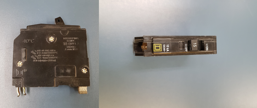
A circuit breaker is an electromechanical device designed to automatically open one or more ungrounded circuit conductors in the event of a fault. They use thermal action and a bi-metallic strip to protect from overload conditions, and a magnetic sensing coil to protect against overcurrent situations. The main advantage that circuit breakers have over fuses is that they are re-settable.
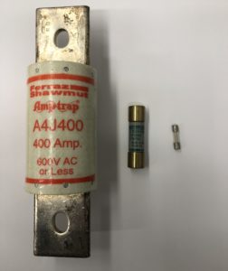
Examples of common fuses
A fuse is a simple device that protects the conductors and equipment of a circuit from damage due to higher than normal fault values. It is designed to be the weakest link in a circuit. It is an insulated tube containing a strip of conductive metal (fuse-link) that has a lower melting point than either copper or aluminum. The fuse link has narrow, resistive segments that concentrate the current and cause the temperature at those points to rise.
During a short circuit the fuse elements burn open in just a fraction of a second. The higher the values of fault current, the faster the fuse will react. In an overload situation, the fuse elements can take many seconds or even minutes before thermal actions cause the fuse link to melt open.
Fuses come in two categories: Fast-acting fuses (Type P) and time-delay fuses (Type D). Fuses used in motor circuits have to withstand the intense inrush current when the motor is first started, and so we install time-delay fuses, also known as “dual-element fuses” in those circuits.
Common Ratings
All overcurrent devices must be operated within their rated values. Three of the most important ratings are voltage, current, and interrupting capacity.
Voltage rating
Fuses and circuit breakers must be rated for at least the value of the voltage of the circuit they are designed to protect.
When a fuse or circuit breaker interrupts a fault current, it must safely extinguish the arc and prevent it from reestablishing itself. Therefore, the voltage rating of a fuse or circuit breaker must be equal to or greater than the system voltage.
For example, a fuse rated at 240V RMS will be acceptable for use in a 120V circuit. However, it would exceed the fuse’s voltage rating to use it in a 600V circuit.
Continuous-duty rating
Continuous-duty rating describes the maximum rated value of RMS current that the overcurrent device is designed to handle on a continuous basis without tripping. Generally speaking, the ampere rating of the fuse or breaker should not exceed the current carrying capacity of the circuit, but there are exceptions, such as certain motor circuits.
Unless otherwise marked, the continuous-duty rating of fuses and circuit breakers is 80% of their marked ampere value. This means that a standard 15 amp circuit breaker is generally designed for use in a maximum 12 amp circuit.
Interrupting capacity
When a short circuit or ground fault occurs, the circuit resistance drops to effectively zero ohms, causing very large values of current to flow. This extremely fast rise in fault current can cause damage to wires and equipment through overheating and must be extinguished as quickly as possible.
The interrupting-capacity (IC) rating of an overcurrent device is the maximum fault current that the device can interrupt without damage to itself. Most circuit breakers and fuses have an IC rating of 10,000 amps.
For systems capable of larger fault currents, high-rupture capacity (HRC) fuses can interrupt currents up to 200,000 amps by using arc-quenching fillers such as silica sand to help interrupt the fault current.
In electrical systems, we use the terms “single-phase” and “three-phase” fairly often, so a brief description of them will help us moving forward.
Single-phase systems are the simplest electrical circuits. They require only two wires: one for power to go in and the other is a return path for current to go out. These are often called Line 1 and Line 2, or Line 1 and Neutral. Current only has one path to travel in a single-phase circuit, and all of the control circuits that we will be looking at are single-phase.
An AC single-phase circuit.
Three-phase systemsare bit more complex. They use three current carrying conductors, called Line 1, Line 2, and Line 3, which have a 120° phase shift in the voltageand current waveforms between them. Each of these conductors are connected to a three-phase load, like a three-phase motor.
When in operation, a balanced three-phase load (such as a motor) has each of its three line’s current values cancel each other out, and so it does not require a return conductor. These loads can be connected in Wye or Delta configuration.
A three-phase circuit
Unbalanced three-phase loads are mainly connected in the Wye configuration where the central point is used as a neutral conductor to carry any stray return currents. In practice a motor is almost always a balanced three-phase load.
Only large industrial and commercial loads will be supplied by three-phase systems. Most heating and cooling loads, especially those used in residential applications, will be single-phase.
Two of the first terms that we will cover are low-voltage release (LVR) and low-voltage protection (LVP).
Sometimes called under-voltage release, low-voltage release (LVR) is a property that circuits have when upon a return of voltage following a power outage, loads automatically turn back on.
Sometimes called under-voltage protection, low-voltage protection (LVP)is a property that circuits have when upon a return of voltage following a power outage, loads will not automatically turn back on and will require further input from the operator.
A simple example of low-voltage release (LVR) and low-voltage protection (LVP) is a simple lighting circuit and a household microwave. Imagine that you are at home, heating something in the microwave (perhaps a burrito) when all of a sudden all of the lights go out. But not just the lights, the microwave and every electrical device not powered by a battery is dead.
Perhaps a tree has fallen across some power lines? Regardless of the cause, the effect is the same: the power is out. This is a common and annoying experience for us all, and often there is nothing to do but light some candles, read a book, and wait.
How do we know when the power has been restored? All of a sudden all the lights come back on, and there’s a beep from the microwave letting you know that the clock needs to be reset.
The lights are an example of low-voltage release (LVR). The switches that control the lights were closed when the power went out, stayed closed during the power outage (the period of “low voltage”), and when the power was restored, the switches were all still in their “ON” position. The load was “released” after the period of “low-voltage.”
Low-voltage release (LVR) is very useful for circuits where re-energization after a brief or temporary loss of power is safe and desirable. Some examples include lighting circuits, sump pumps, refrigeration circuits, and ventilation circuits. These are examples of circuits where their failure to re-energize after a power disruption could lead to damage of property (sump pump) or endangerment of safety (parkade ventilation).
The microwave was an example of low-voltage protection (LVP). The timer controlling the microwave shut off when the power went out, and when the power returned, the control circuit of the microwave waited for further input from a human operator.
Low-voltage protection (LVP) is desirable when the sudden activation of a machine or other electrical load could cause damage or injury. Some examples would include any rotating machinery (table-saws, lathes) or moving conveyor belts. These are examples of circuits where the sudden re-energization could surprise or injure a person working nearby.
There are many ways that circuits can be equipped with either low-voltage release (LVR) or low-voltage protection (LVP), but two of the simplest are with two-wireand three-wire control circuits respectively.
As a rule, if a circuit uses a magnetic contactor and a holding contact, it will provide low-voltage protection (LVP).
If it uses maintained contacts, then it most likely provides low-voltage release (LVR).
If using the print, PDF, or eBook copy of this book, navigate to the above link to complete the quiz. However, the quiz questions are also provided at the end of the book for offline use: Offline Copies of Chapter Quizzes.
Heating
II
Click play on the following audio player to listen along as you read this section.
Heating modern buildings is one of the most important functions that HVAC systems can provide. The energy required to heat a space or a house comes from either the burning of natural gas, or it comes from electric heating loads. The method of distributing heat throughout a building can also vary, depending on the medium used to transport the heat. Usually forced air or water is used, though some heating loads, such as baseboard heaters, rely on passive heat dissipation.
Control of heating loads requires temperature sensitive switches, called thermostats, which can either directly, or indirectly control the heating equipment.
Thermostats – General
7
Click play on the following audio player to listen along as you read this section.
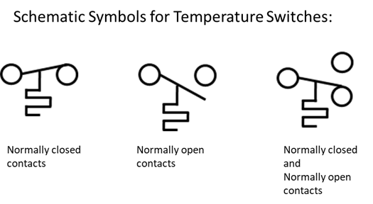
Thermostats are what we refer to as “temperature-actuated switches,” meaning they will automatically open or close their electrical contacts upon a change in ambient temperature. This means that we can set the thermostat in the room to a comfortable level and allow the heating or cooling system regulate the temperature.
Thermostats that control heating loads will close their contacts when the temperature falls below its set point, while thermostats controlling cooling loads will energize upon a rising temperature. Some systems will allow a single thermostat to control both heating and cooling apparatus.
Schematic symbols for temperature-activated switches.
Inside the average residential home, thermostats are generally found in two varieties: line-voltage thermostats, which directly control the flow of current to the load, or low-voltage thermostats, which indirectly control current to the load.
Regardless of the type of thermostat used, it must be rated for the voltage and current that it is expected to operate at and control.
The location of thermostats is critical as well. As a rule, we place our heaters, either baseboard heaters or air vents, near the outside of rooms and near windows and other areas of high heat loss. For the most effective heating of a room, thermostats should be installed on the opposite wall, or as far away as possible from a heat source.
If the thermostat was installed directly above the heater, for example, it would sense a high temperature and switch the load off long before the room heated up to a desirable level. By installing it on the opposite wall, we ensure the heat has to travel through the whole room before the sensor opens the circuit, providing more balanced heating.
Some thermostats will have the temperature sensitive portion of their apparatus installed remotely from their electrical contacts. This type of thermostat is commonly used for in-floor heating and certain industrial processes, where temperature monitoring equipment is impractical to install.
Line Voltage Thermostats
8
Click play on the following audio player to listen along as you read this section.
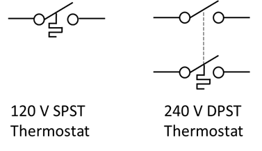
Line-voltage thermostats are available as either single-pole single throw (SPST) or double-pole single throw (DPST) switch types and are popular for use with baseboard heaters. They are relatively inexpensive and act as on/off switches to conduct full power to the heater load.
Line-voltage thermostat contacts.
Used most commonly with multiple baseboard heaters, line-voltage thermostats must be installed in each room or heated area to allow precise control of heat.
For example, it is common to install a baseboard heater under the window in every room with an exterior wall and have one thermostat near the entrance to that room, either above or beside the light switch, to control that individual heater. This ensures that the whole room will be heated before the thermostat clicks off, but that the unoccupied room next door does not heat up.
Since heating loads are energized at 240V for increased efficiency, thermostats controlling them are not allowed to have a marked “OFF” position unless they open all ungrounded conductors. This means that only a double-pole, single-throw (DPST) thermostat will have an “OFF” position, while a single-pole, single-throw (SPST) thermostat will instead be marked “LOW” or “MIN.”
Regardless of the type of thermostat used, NEVER use a thermostat as a disconnecting means before working on a baseboard heater. Disconnect the power at the source and verify it is dead before working on any voltage source.
Line-voltage thermostats must be rated for the voltage, current and power ratings of the loads they will be controlling. For example a thermostat rated at 240 volts and 2880 watts must only be used to control maximum 12 amps of load current.
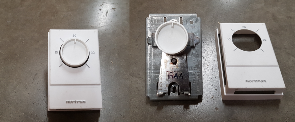
A standard SPST line voltage thermostat
Low-Voltage Thermostats
9
Click play on the following audio player to listen along as you read this section.
Low-voltage thermostats are smaller and cheaper to install and maintain, and the wiring does not need to have as high a voltage and power rating as their line-voltage counterparts. This is why low-voltage control circuits are favoured for central heating units. Low voltage thermostats are also more sensitive to changes in heat than line-voltage thermostats, and so can provide more precise control.
When controlling a single large heating unit, such as a central gas furnace or electric furnace, there is no zone control as with baseboard heaters; either the whole house is getting heated, or none of it is. A low-voltage thermostat installed in a central location, and powered by a 120 - 24V transformer, can senses the ambient temperature and be used to control a relay to deliver power to the heating load.
By using an extra-low-voltage source for the control circuit we get the benefit of lower cost and easier installation along with increased safety, allowing a simple two-wire low-voltage cable to be installed in an ideal location in the house. Because it is only meant to handle the control current and not the load current, low-voltage thermostats are highly responsive and can provide more accurate control than line-line voltage thermostats.
Some models of low-voltage thermostats used to control central gas furnace or electric furnace loads incorporating heat exchanges and blowers, will have a small, series connected, resistive device called an anticipator resistor. The purpose of this device is to fine tune the sensitivity of the thermostat and prevent overshoot of the desired room temperature.
Low-voltage thermostats, fall into two general categories, some are simple temperature activated switches while others are more modern electronic thermostats incorporating solid-state circuitry and allowing for programmable behaviours such as 24-hour cycles, and weekday vs weekend scheduling.
Electronic thermostats use semiconductor components for both temperature sensing and control-circuit switching. If installed to replace an existing analogue thermostat, the electronic thermostat must have a separate power source, which is usually a battery.
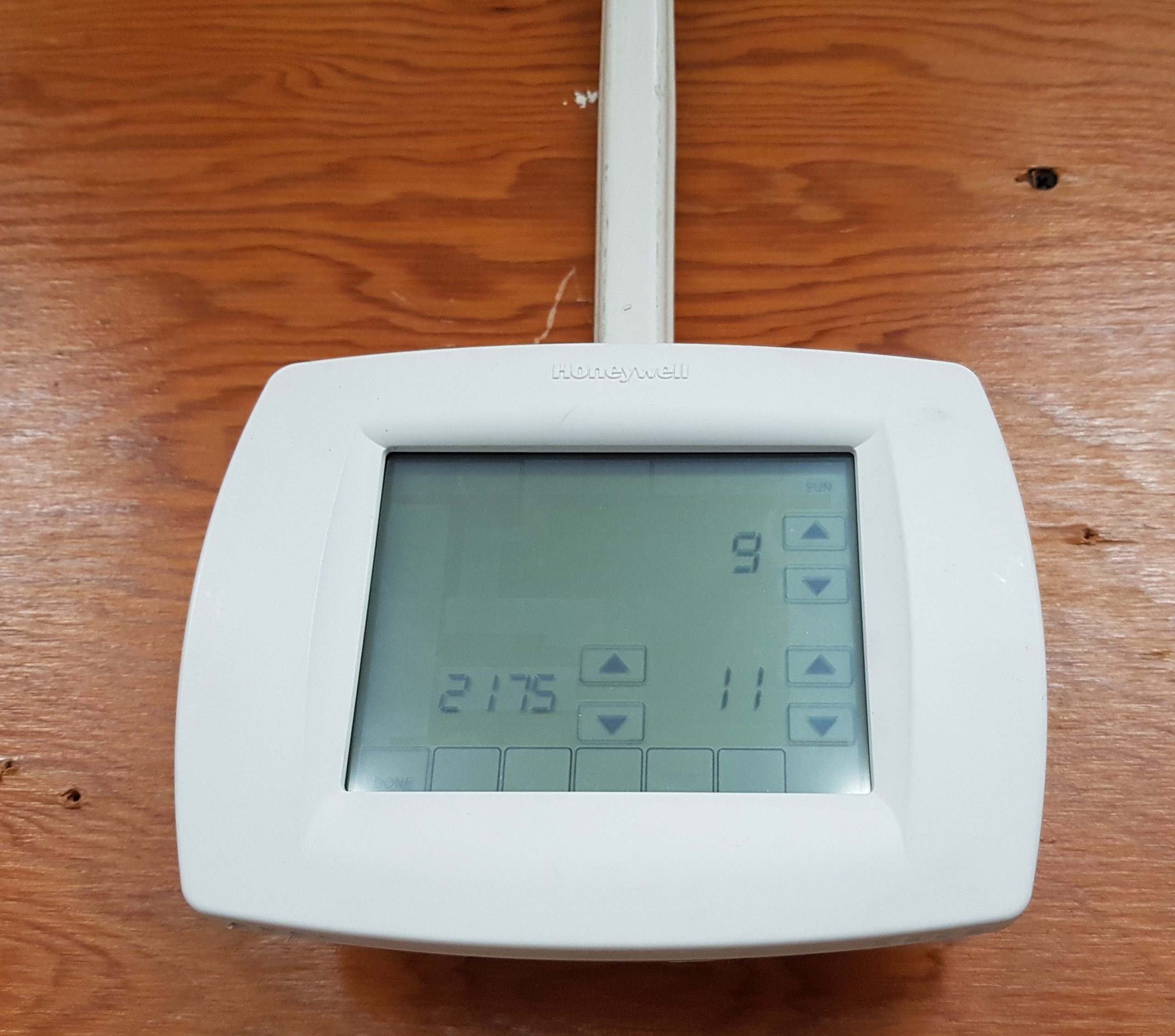
An example of a programmable thermostat.
Electric Heat – General
10
Click play on the following audio player to listen along as you read this section.
There are several main styles of fixed electric heating loads, including baseboard heaters, unit heaters, heating cable sets (in-floor heating) and central electric heating, which is similar to central gas heat, in that there is one source that distributes heat, usually by blowing warmed air through ductwork.
Electric heating loads are very reliable methods of heating a building. By passing current through a resistive element, our electric heaters produce heat proportional to the square of the applied voltage.
This means that if you connect your heating load at half its rated voltage, you will produce one quarter of the power, or consequently if you connected at twice the loads rated voltage you would develop four times the rated power. It is for this reason that fixed electric heating loads are connected at 240V, which is the line-to-line voltage inside most houses.
Baseboard Heat
11
Click play on the following audio player to listen along as you read this section.
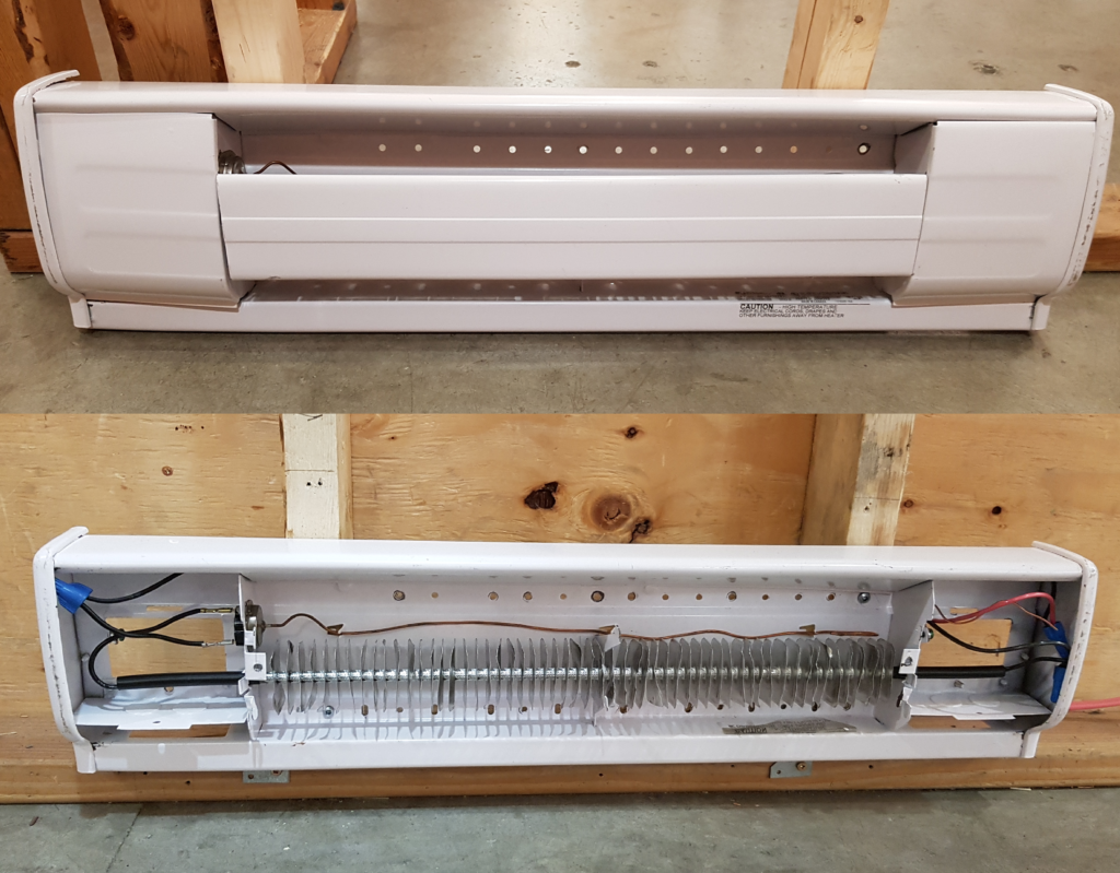
The simplest form of fixed electric heat is the baseboard heater. These small, modular units with their long horizontal profile are installed underneath windows and other areas of high ambient heat loss.
An example of a baseboard heater, both with the cover on, and with the heat fins and wiring connections exposed.
Energized at 240V in households to maximize heat production, baseboard heaters are commonly controlled by line-voltage thermostats installed in each room or heated area though some can also be controlled by built-in thermostats installed directly into the unit housing.
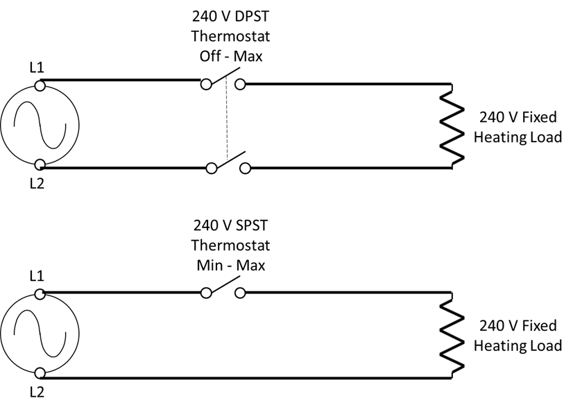
Control methods for 240V baseboard heaters.
Because line-voltage thermostats directly control the flow of current to the heater element they must be rated for whatever value of current flows through them.
Baseboard heaters are rated for their power output, in watts, and are generally available in 250W increments, thus allowing installers to select the appropriate size of heater for the area being heated. To find the current requirements of a device, divide the rated power by rated voltage.
For example, a thermostat rated 3kW at 240V would be able to handle 12.5 amps of current.
When installing any kind of baseboard heaters, care must be taken not to install any other electrical equipment above them. No receptacles may be installed above a baseboard heater because of the risk of a cord resting on the heater and getting damaged by the heat. If a receptacle is required in a section of wall that also has baseboard heat, some manufactures will provide spacing inside the heater for installation of a receptacle.
Central Electric Heat
12
Click play on the following audio player to listen along as you read this section.
A central electric furnace is comprised of a large bank of resistive heating coils, and a blower motor that pushes air across them. Most furnaces allow for the installation of air filters to help purify the air as it circulates through the building.
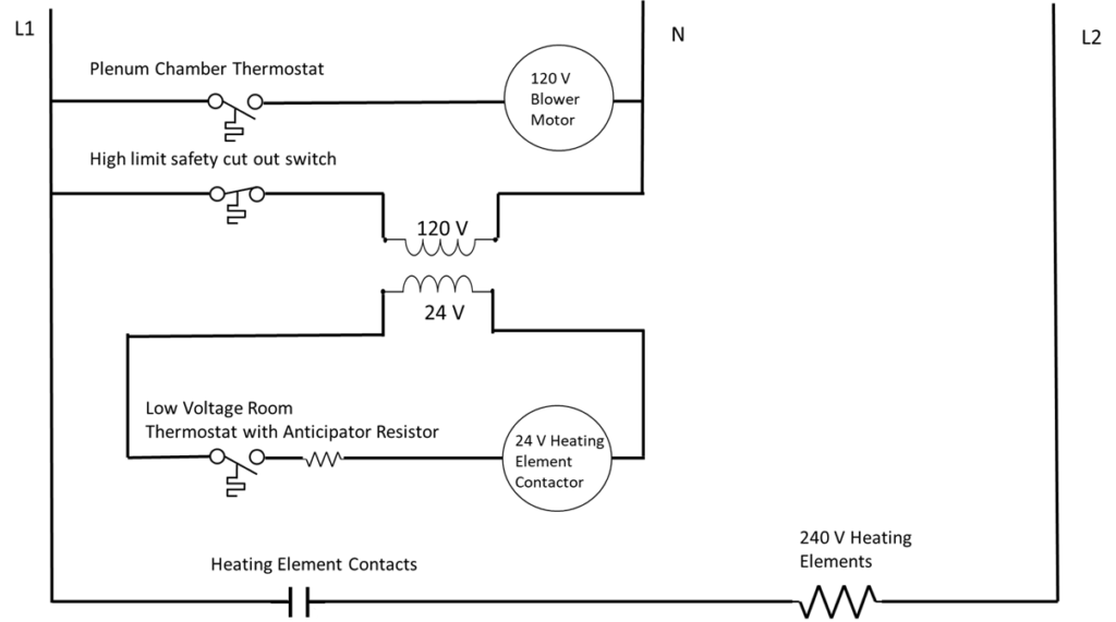
Control of the furnace comes from a low-voltage thermostat installed in a central location of the house. This room thermostat energizes a 24V solenoid contactor, which in turn energizes the 240V heating elements. As the temperature in the plenum chamber rises, eventually the blower motor thermostat engages and begins to push heated air throughout the building.
A central electric furnace control circuit
The furnace houses the relays which control the heating elements. These are normally switched on and off in increments of 5 kW or less. This helps reduce the strain on the line due the heavy currents drawn when large heating loads are all switched on simultaneously. This helps reduce the flickering of lights and other under voltage concerns in parallel circuits.
The furnace will also contain a high temperature safety cut-out switch that will disconnect all power to the heating elements if the temperature rises above a pre-set safety threshold. This can happen if the blower fan fails to engage and drive the heated air through the house, and thus draw cool air into the plenum chamber.
Electric furnaces are sized according to their power consumption and can generally range anywhere from 5 kW to 40 kW, and be supplied with either single-phase voltage for household use, or three-phase voltage for industrial and commercial heaters, depending upon the availability at the point of installation.
Unit Heaters
13
Click play on the following audio player to listen along as you read this section.
Unit heaters are often installed at ceiling height or recessed into a wall, and consist of a heating element, a built in blower fan and louvers to direct the direction of heated airflow. They are small and compact in size, yet have a high capacity for heating a room or area.
If a single unit heater is to be installed, its heated airflow should be directed towards the area of highest ambient heat loss, such as a window or door, however care should be taken to make sure that no surface is heated beyond a safe level.
If multiple unit heaters are installed their air flow should be directed in a circular motion along the exposed outer walls.
Control of unit heaters is similar to that of baseboard heaters, in that there must be a temperature activated switch, either installed directly on the heater unit, or more effectively, in another part of the room. A built-in fan switch is also provided to allow the fan to circulate air during warm weather without energizing the heater elements.
Unit heaters are available anywhere from 2 kW to 60 kW, with units on the lower side, up to approximately 5 kW usually being single-phase AC and controlled by low-voltage thermostats and relays, while units rated above 5 kW are usually three-phase.
Portable Heaters
14
Click play on the following audio player to listen along as you read this section.
Portable electric heaters, such as a temporary space heaters, will operate at 120V because this is the output voltage of standard receptacles. These smaller heating loads can be moved from room to room to allow for flexibility in heating options. Portable heaters will have a thermostat built into them to automatically switch off the heater once the room has reached the preset temperature. Some may include a fan to help drive warm air through the space being heated.
In-Floor Heating
15
Click play on the following audio player to listen along as you read this section.
As anyone who has walked on a cold tiled floor in their bare feet can attest, nobody likes cold toes. Likewise, anyone who has shovelled snow off their driveway or sidewalk will agree that not dealing with snow would be far superior. The good news is that in-floor heating exists to help ameliorate these situations.
By installing resistive heating cables below the finished floor, such a tiled floor in a bathroom, we can eliminate the heat sapping characteristics of the cold tiles, however underfloor heating sets are not intended to be a source of heat for the room.
Heating cables can also be installed below driveways and walkways for the purpose of melting ice or snow in the winter. When laid in concrete, cables must be of a material that is resistant to any chemical reaction.
This is a similar process to installing heat trace cables for freeze protection on plumbing, and drain piping.
Some manufactures produce heating cables that are embedded in mats which are laid out below the tiled floor to be installed, in which case cable spacing is not a problem. If the heating cable comes on a roll, the cable is usually installed at a spacing of about 150 mm to 300 mm. Regardless of the style, they are commonly designed for a loading between 40 and 160 watts per square meter.
One of the most important details to keep in mind is to never shorten the length of cable when installing in the field. Doing so would change the series connected resistance of the cable, and thus change the current drawn and the power dissipated by the cable, perhaps beyond safe conditions.
The system can be controlled by a wall mounted thermostat that has a remote sensor embedded in the floor to sense floor temperature.
Gas Heat – Basic Principle
16
Click play on the following audio player to listen along as you read this section.
One of the most common ways to heat a home or other type of building, is with a gas-fired furnace. In contrast to an electric furnace, a gas fired furnace converts the stored chemical energy in methane rich natural gas to produce heat. While natural gas is cleaner than other fossil fuels, it still emits carbon when consumed, and so it is a greenhouse gas emitter. Its chief benefit is that it is often a cheaper alternative to expensive electric heating bills.
Natural gas is used to provide space heating by heating either air, in a forced-air system, or water, in a hydronic heating system. Both systems rely on either pumps or fans to push either the heated air or water throughout the building.
Basic Principle
A gas fired forced-air furnace operates on a similar principle as a central electric furnace. Both require a control circuit to sense the temperature of the space to be heated, and a fan to circulate air throughout that space. The furnace is usually located in the basement or crawl space of a house.
If the room temperature falls too low, the main thermostat clicks on and opens the main gas valve which allows the combustible gas to fill the heat exchanger. The inflowing gas is ignited via a pilot light, direct spark ignition, or an electrically heated hot-surface igniter similar to a diesel engine glow plug. Once the temperature in the heat exchanger has risen to a sufficient level, a local thermostat or timer switch engages the blower fan.
An upper-limit safety thermostat is installed in the plenum chamber to disengage the main gas valve should the blower fan fail to engage, and the temperature rise too high.
The blower fan pushes the heated air through the ducting system and the building, usually via floor registers. Since hot air rises, it is always more efficient to install heat registers as low as possible and near places of high ambient temperature loss, such as windows and exterior walls or doors. Return-air registers draw cooled air back down to the furnace and the heat exchanger to be warmed again.
As the blower fan draws the return air, it pushes it through a filter before heating it again. This helps maintain healthy air quality levels in the building, and filters should be replaced regularly.
If a hydronic heating system is used instead of a forced-air system, a pump will push the heated water to radiators throughout the building to dissipate their thermal energy.
One of the by-products of combusting gasses to produce heat, is smoke, which needs to be vented safely away from the house. The heat exchanger keeps the toxic byproducts of combustion separate from the air that is circulated throughout the building. Most of the heat is transferred to the circulating air, but some still lost through exhaust. Older heat exchangers had an efficiency of roughly 50%, meaning half the heat produced was wasted up the chimney. Modern designs have improved efficiency to approximately 70% to 80%, and recent high-efficiency furnaces can achieve heat distribution efficiencies above 90%.
Gas Heat – Control
17
Click play on the following audio player to listen along as you read this section.
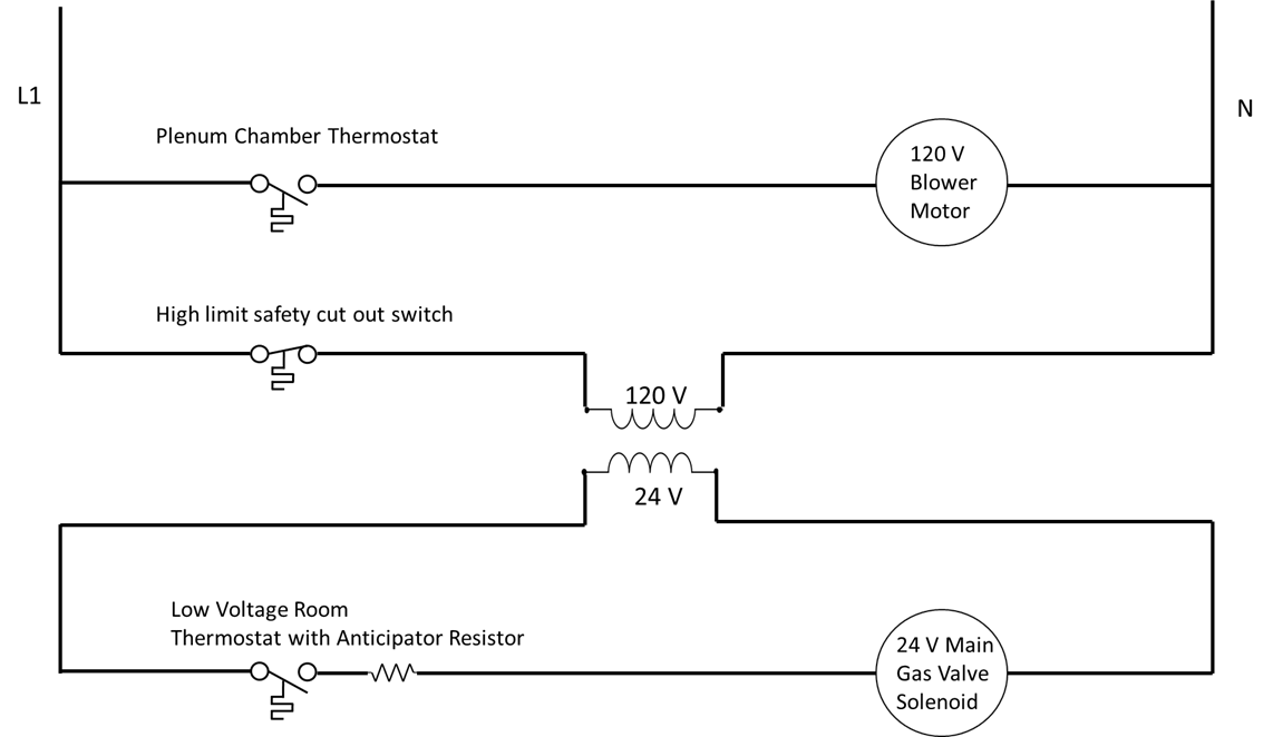
The control of a central gas heating system is fairly simple. An extra-low-voltage, 120 to 24 V transformer provides the power for a control circuit, while a dedicated 120 V low-voltage circuit provides power to the blower fan. Extra-low-voltage conductors connect the furnace to the room thermostat.
Control circuit for gas-fired furnace
When the room temperature gets sufficiently low, the room thermostat clicks shut, and the completed circuit opens the main gas valve. The inrushing gas is then ignited and begins to heat the air in the heat exchanger.
It is important that the heat exchanger isolate the products of combustion from the heated air that is to be circulated through the house. Once the temperature in the heat exchanger reaches a sufficient level, a second thermostat inside the furnace housing clicks shut and engages the blower motor.
When the heated air causes the temperature in the house to rise sufficiently, the main room thermostat contacts will open, de-energizing the main gas valve, thus cutting off the gas supply and extinguishing the burner flame.
Though the main gas valve has now been closed and the flame extinguished, the heat exchanger is still very hot, and so the blower motor continues to run, dissipating and distributing any residual heat. This will continue until the blower motor thermostat senses a sufficient drop in plenum chamber temperature, and opens its contacts.
This residual heat would normally cause overshoot of the desired room temperature, and so the low-voltage thermostat may incorporate a series connected, anticipator resistor, which creates a small amount of heat causing the thermostat to open before the set temperature is reached. A few minutes after the thermostat opens, the blower control thermostat opens, de-energizing the blower motor, and the room reaches the desired temperature.
The furnace will also contain a high temperature safety cut-out switch that will disconnect all gas to the heating elements if the temperature rises above a pre-set safety threshold. This can happen if the blower fan fails to engage and drive the heated air through the house, and thus draw cool air into the heat exchanger.
Pilot Lights
18
Click play on the following audio player to listen along as you read this section.
Many gas-fired systems incorporate a pilot light to ignite the gas when the furnace is first turned on. A pilot light is a steady flame which is always present. It is fed by a normally-closed valve which is held open by a solenoid coil, and allows a small amount of gas through at all times. When the room thermostat engages the heating system and the main gas valves open, the in-rushing gas is instantly ignited by the pilot light flame.
If the pilot light was to ever extinguish, a danger might be presented if the flow of gas was allowed continue without combusting. It is for this reason that the valve is designed to automatically close if the flame should ever extinguish. To achieve this, a thermocouple is used to keep the valve open.
Spark ignition and electronic ignition, sometimes called a glow coil, are alternative methods of igniting the gas used for heating. All rely on the principle of instantly igniting the gas once the main gas valve opens.
Thermocouples
19
Click play on the following audio player to listen along as you read this section.
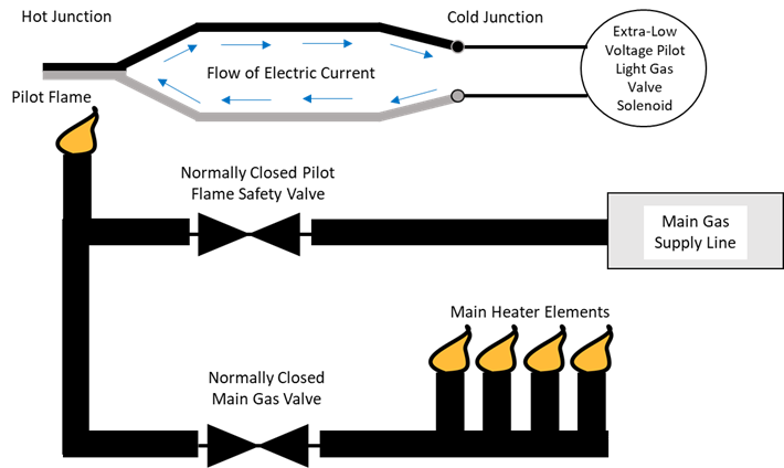
A thermocouple is constructed from two dissimilar metals that utilize thermoelectric generation to create a small voltage when heated. When one junction is subjected to presence of heat at the pilot light flame, a small DC current flows through the cold junction of the thermocouple, which is connected to the pilot safety shut-off gas valve circuit.
Thermocouple and pilot light safety control circuit.
If the pilot flame is extinguished, the voltage source disappears and the normally closed, held-open valve re-closes, thus preventing gas from filling the space.
This small value of voltage, usually around 25 – 30 DC millivolts, provides the power to hold the pilot light valve open during normal operation. The types of metals used in the construction of the thermocouple depend upon the values of temperature they are to be subjected to.
If a higher value of voltage is required, a thermopile, which is manufactured from several series-aiding connected thermocouples, can provide voltages of typically 250 DC millivolts or 750 DC millivolts. Certain stand-alone gas fired furnaces and fire-places will utilize a thermopileto provide control circuit power to a low-voltage thermostat installed in the room.
Hydronic Heating Systems
20
Click play on the following audio player to listen along as you read this section.
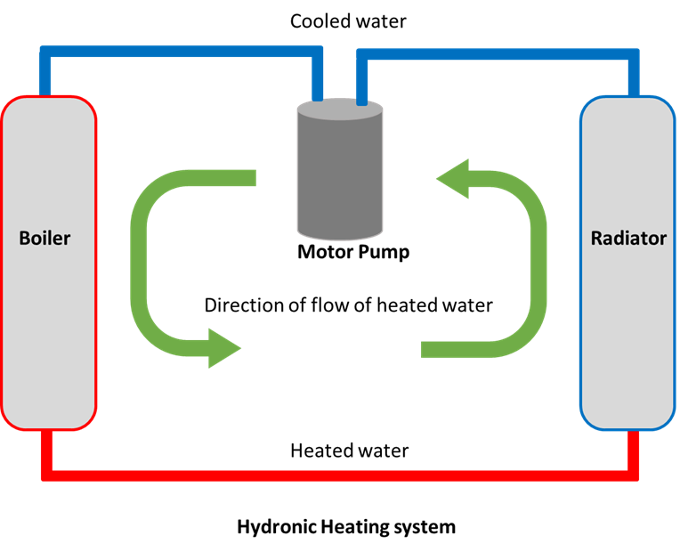
One of the simplest methods of heating a room is to pass warmed water through pipes in that room. If the ambient temperature in that room is lower than that of the water in the pipes, they will release some of that stored heat energy. If the water did not move, it would quickly reach equilibrium with the room and no more heat transfer would occur. By constantly cycling fresh, warm water through the pipes, and carrying away the cooled water, an energy transfer can take place, with water as the medium that carries the energy.
This system would require an external heating source, such as a gas-fired boiler or an electric boiler to heat the water. Once the water has collected this stored thermal energy, it is then cycled through the system, transferring heat energy in the desired locations. Radiators are usually installed near windows and points of high heat loss to release the stored energy.
Hydronic heating system.
Self Test 2
21
Take the following self test as many times as you like.
If using the print, PDF, or eBook copy of this book, navigate to the above link to complete the quiz. However, the quiz questions are also provided at the end of the book for offline use: Offline Copies of Chapter Quizzes.
Ventilation
III
Click play on the following audio player to listen along as you read this section.
Efficient movement of air through a building is a critical component of any forced-air HVAC system. A furnace or air conditioner unit will either heat or cool the air before an air-handling unit, consisting of a motor driven fan, pushes the treated air through the ducting system which channels it throughout the building. The air-handling unit must be capable of overcoming the static air pressure demands of the ducting system, which act to oppose air flow.
Another important aspect of properly ventilating a building is circulating fresh air from outside the building with the heated, or cooled air that is driven through the ductwork. This helps keep fresh, oxygen rich air at safe and healthy levels, and stops the buildup of carbon dioxide inside the building.
Pressure Terms
22
Click play on the following audio player to listen along as you read this section.
Static pressure: The force required to move air through various components, such as filters, dampers and diffusers. This represents a resistance to air flow.
Static pressure is the outward force of the air in the ducts and represents a waste or loss of available pressure. Anything that adds air resistance, such as corners in ducting and filters will increase the static pressure.
Velocity pressure: The force exerted by a moving air stream. It is produced in the direction of the moving air. This represents the useful value of pressure that moves air through the ductwork.
Total pressure: The sum of static and velocity pressure inside an HVAC system; the total opposition to airflow in a ducting system.
An air-handling unit will have a maximum value of pressure that it can produce. If static pressure is too high relative to velocity pressure, the fan will be unable to circulate air throughout the ducting system. Most air handling units will have a maximum pressure rating that they are designed to deliver.
In testing HVAC systems, it is sometimes necessary to test the pressure at various places. Direct measurements can give values for static or total pressure, from which the velocity pressure can then be derived.
Fans and Blowers
23
Click play on the following audio player to listen along as you read this section.
Sometimes called the air-handler unit or the blower, the fan is the device which drives the treated air throughout the building. Usually driven by a single-phase AC motor in smaller applications, and a three-phase motor in larger commercial or industrial applications.
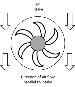
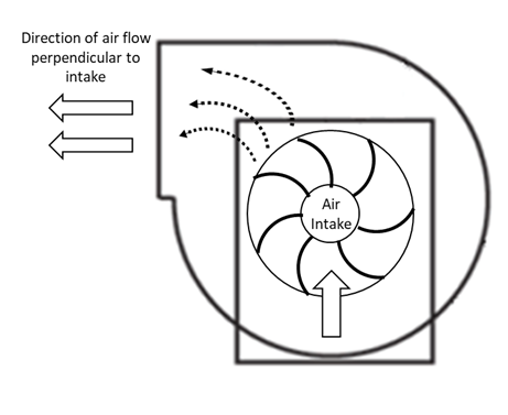
There are two main categories of fans, each with their own advantages and applications: the axial fan, which draws air parallel to the rotating axis and the centrifugal fan, which draws air at a right angle to its rotating axis.
Axial Fan
24
Click play on the following audio player to listen along as you read this section.
Axial fans are designed for moving low volumes of air under low static pressure conditions.
Axial fan
In their most basic shape an axial fan resembles an airplanes propeller, and simple household fans utilize this design.
While the propeller design is the simplest, there are other styles of axial fans. The tubeaxial, which is simply propeller-style blades installed in a ducting tube to help direct and focus air flow, and the vaneaxial, which incorporates air straightening vanes down behind the blades, and boasts the highest efficiency of the axial fans.
Due to their lower power requirements, axial fans are usually powered by single-phase AC motors which are either driven directly or via a belt system. They are generally quiet in operation and are favoured in places where noise levels are a factor, but are not suitable for moving large volumes of air.
These styles of fans are often used to drive fresh air over the condenser coils in rooftop units of air conditioning systems.
Centrifugal Fan
25
Click play on the following audio player to listen along as you read this section.
Centrifugal fans are better suited to push larger volumes of air through ducting systems. They are designed to produce higher pressure for a given volume of air than an axial fan of the same horsepower rating. Any fan used to drive air throughout the system must produce enough total pressure to overcome the static pressure of the ducting system and drive air everywhere it is needed.
Centrifugal fan
Drawing the intake air at 90 degrees relative to the outtake, the fan blades direct the air in an spinning, circular direction, accelerating it towards the exhaust vent.
Depending upon the application, the drive mechanism of the fan may be directly coupled, belt driven, or powered by a variable speed drive.
Centrifugal fans are noisier than an axial fan of equivalent horsepower, and so are often installed in areas where high noise levels are acceptable or noise dampening components can be installed.
Centrifugal fans can move large quantities of air, while overcoming all the resistive static pressure of the duct-work system.
Fan Substitutions
26
Click play on the following audio player to listen along as you read this section.
There are three important considerations to keep in mind when changing the motors of HVAC fans, if a change in speed or horsepower is also involved.
The first is that airflow varies directly with fan speed, so doubling the speed of the fan will double the airflow.
The second is that static pressure varies with the square of the fan speed, so that doubling the fan speed will quadruple the static pressure in the ductwork.
The third consideration is that electrical power consumed by the motor varies with the cube of the fan speed, so that it requires a motor with eight-times the horsepower rating of the previous motor to double the fan speed.
This will result in a very significant change in the demand of the electrical draw of the motor. Be sure not to exceed the current, voltage, or horsepower ratings of any electrical circuits, or overcurrent devices.
Dampers
27
Click play on the following audio player to listen along as you read this section.
Dampers are devices installed in the ductwork of air systems to regulate the flow of air. They can be controlled manually or remotely and can be used to ensure a certain percentage of the return airflow is mixed with incoming air from outside. This helps ensure that healthy levels of fresh air are added to the recirculating air flow system.
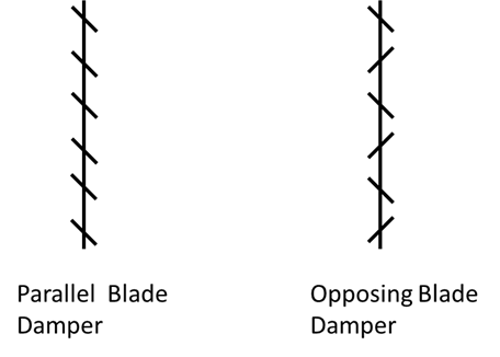
Most sets of dampers consist of a U-channel frame with several connected sheet-metal blades which are driven by a small motor. The edges of the sheet-metal blades will have rubber seals to help provide a tighter barrier to air when in the closed position.
Parallel and opposing blade dampers.
Dampers are divided into two categories depending upon how their blades rotate relative to each other. Opposed blade dampers are constructed so that adjacent blades rotate in opposite directions, while parallel blade dampers have all blades rotating in the same direction, similar to Venetian blinds.
Motor driven dampers that are part of larger commercial or industrial HVAC systems will have power-fail positions that they will revert to in the event of a loss of voltage.
Motor driven dampers are controlled by actuators, which contain a spiral spring inside their housing that tightens clockwise as the motor is driven. This spring provides the stored energy to return the sheet-metal blades back to their original position should electrical power be disconnected from the actuator. When installing actuators care must be taken to ensure that in the event of a power failure the spring in the actuator returns the damper blades to the desired default power-fail position.
Outside and exhaust dampers will generally revert to a normally-closed (NC) position, while return air dampers will revert to their normally-open (NO) position to ensure that any supply fans are not deprived of fresh air.
Self Test 3
28
Take the following self test as many times as you like.
If using the print, PDF, or eBook copy of this book, navigate to the above link to complete the quiz. However, the quiz questions are also provided at the end of the book for offline use: Offline Copies of Chapter Quizzes.
Mechanical Cooling
IV
Click play on the following audio player to listen along as you read this section.
Mechanical cooling refers to any of several methods that use energy to actively remove heat, or thermal energy, from one location and dissipate it elsewhere. Mechanical cooling is governed by the principles of thermodynamics, gas pressure laws and the energy intensive properties of rapidly evaporating refrigerants.
All mechanical cooling systems rely on an electric motor to power a pump or compressor, which drives the cooling medium throughout the system.
Mechanical Cooling – General Applications
29
Click play on the following audio player to listen along as you read this section.
Mechanical cooling has a wide range of applications; it is used in automobiles, rooftop HVAC units, coolers, refrigerators, freezers and even in the chiller units that produce the cold water for hydronic cooling coils. Mechanical cooling is utilized for the large scale cooling of entire buildings, or it can be used to keep the inside of the fridge cold and allow for the long term storage and freezing of food.
Air conditioning units use the basic Direct Expansion (DX) cooling cycle in a process that removes heat from one area where it is not desired, and transfers that heat to an area where it is quickly dissipated. The air conditioner itself does not create heat, nor does it destroy heat—it simply transfers heat from a room into a refrigerant, and then from inside the building to outside.
Hydronic chiller systems may use a DX system to bring large quantities of water below room temperature, and then pump this cooled water throughout the building to lower the average temperature. Often used in association with rooftop water coolers to rapidly release thermal energy collected in the building.
Heat pumps are a type of DX cooling system that allows for the refrigerant to flow in both directions through the system. By reversing the direction of the flow of refrigerant, a heat pump can go from cooling a house in the summer, to warming that house in the winter, all while using the same equipment. This can simplify the installation and allow a single system, rather than separate heating and cooling components, to regulate the temperature of the building.
Mechanical Cooling – Principles
30
Click play on the following audio player to listen along as you read this section.
Mechanical cooling, or refrigeration, refers to any method that uses energy to actively cool an area. Examples include refrigerators and freezers, air conditioner units and heat pumps. Regardless of the scale of the cooling system, whether air conditioning a building or keeping the inside of your refrigerator cold, all cooling systems are governed by the first two laws of thermodynamics:
Energymay be neither created nor destroyed, but may be changed from one form to another
Accordingly, thermal energy or heat may not be created to warm an area nor destroyed to cool an area. Instead we use heaters to convert either stored chemical energy (gas) or electrical energy into heat, or we use cooling systems to remove heat from a given area.
Thermal energyalways flows spontaneously in the form of heat from regions of higher temperature to regions of lower temperature, increasing the entropy of the system.
An object or area that is hotter than the ambient temperature surrounding it will naturally release heat until equilibrium is established and there is no longer a temperature gradient. A bowl of hot soup will cool to room temperature over time. Conversely, objects that are colder than the ambient temperature will absorb thermal energy until they reach ambient temperature. This fundamental relationship underlies the principle behind many styles of mechanical cooling systems, including DX, or direct expansion cooling.
Hydronic Cooling Systems
31
Click play on the following audio player to listen along as you read this section.
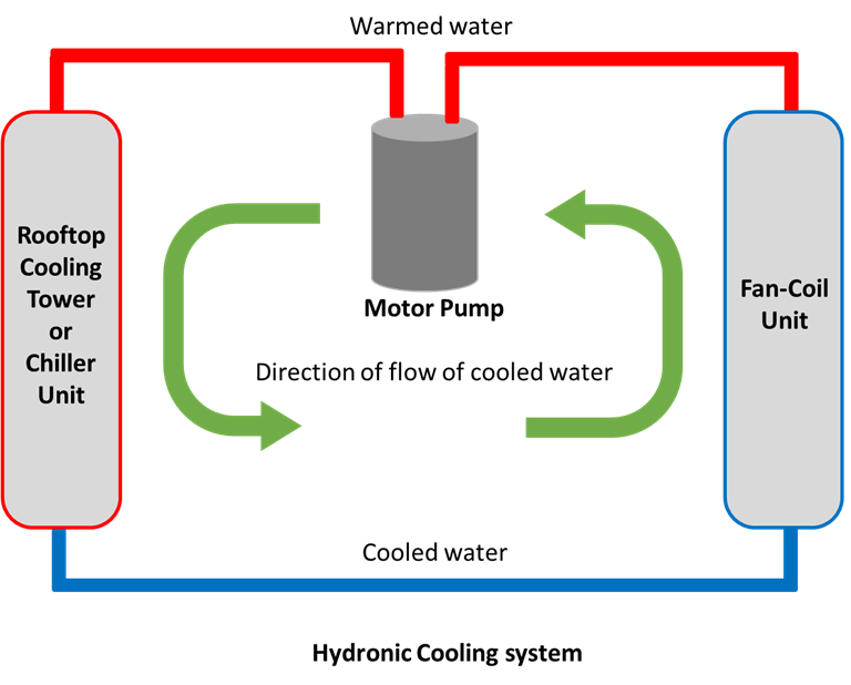
One of the simplest methods of cooling a room is to pass chilled water through pipes in that room. If the ambient temperature in that room is higher than that of the water in the pipes, they will absorb some of that heat energy. If the water did not move, it would quickly reach equilibrium with the room and no more cooling would occur. By constantly moving fresh, cold water through the pipes, and carrying away the warmed water, an energy transfer can take place, with water as the medium that carries the energy.
Hydronic cooling system
This system would need some place to dissipate the thermal energy of the room. The water is usually driven to a unit mounted outside of the building, often installed on the rooftop of larger installations, and heat is dissipated into the ambient environment. This method requires that the ambient environment is cooler than the water in the pipes, because with out a temperature gradient, no thermal energy will spontaneously flow from the warmer water in the pipes to the cooler air surrounding it.
Once the water has dissipated its stored thermal energy, and its temperature drops, it is then cycled through the system again, to transfer more heat energy from one area to another.
Some hydronic cooling systems may run pipes deep underground where there is often a steady and reliable temperature gradient between surface and below ground temperatures. This provides a consistent, and energy efficient method to dissipate thermal energy.
This type of system will sometimes incorporate additional cooling components, such as direct expansion cooling (or DX cooling) to further lower the temperature of the chilled water before it returns to the room to continue the cooling process.
Gas Laws
32
Click play on the following audio player to listen along as you read this section.
Before we can examine the inner workings of direct expansion cooling systems, it will help to have a basic understanding of how fluids and gasses behave under different conditions. Specifically we are concerned with how changes in pressure, temperatureor volume will affect our cooling systems.
Pressure is defined as a force acting upon an area. Expressed mathematically
Pressure is directly proportional to the force, in (N) newton’s and inversely proportional to the area, in (m2) square meters, upon which it acts. By changing either the force or the area, we can vary the pressure of a system.
Temperature is the thermal energy contained by a material as its atoms collide with each other. It is a representation of kinetic energy. The hotter an object is, the more kinetic energy it atoms have, and the more collisions will occur.
It takes energy to heat something, and a hot object will slowly cool by dissipating its kinetic energy to the outside environment.
Temperature is measured in either degrees Celsius (C°) or degrees kelvin (K°) . Kelvin is the base unit of temperature in the SI system.
Volume represent the given space that something occupies. When describing gasses or liquids we often describe the volume that they take up. measured in cubic centimetres (cm3) or more commonly, (L) liters.
When compared, we find that the temperature of a system is directly proportional to its pressure and inversely proportional to the volume that it occupies.
Expressed mathematically:
This equation is a simplification of more complex gas laws, but will serve to illustrate the relationships that we wish to focus on.
In our DX cooling systems we will control the volume and pressure of a medium, the refrigerant, to transfer heat from one place to another.
Phase Changes
33
Click play on the following audio player to listen along as you read this section.
We are relatively familiar with the three main forms of matter: solids, liquids and gasses. Since cooling systems make use of the changing properties of a refrigerant as it goes from liquid to gas form, it is useful to understand the relationships between temperature and heat energy in a system.
Solids are defined as having a low heat-energy level, meaning the atoms are locked in place and the object has a fixed volume and shape. For example a block of ice is water in its solid form.
As ice melts it becomes the liquid water that we are all familiar with. Its atoms are free to flow about, and it has a fixed volume, but will spread out to fill whatever container it is in, meaning its shape is not fixed.
As water is heated, it eventually boils and becomes a gas. In this state, its atoms are free to move about, and it has no fixed shape or volume. This is its highest energy level.
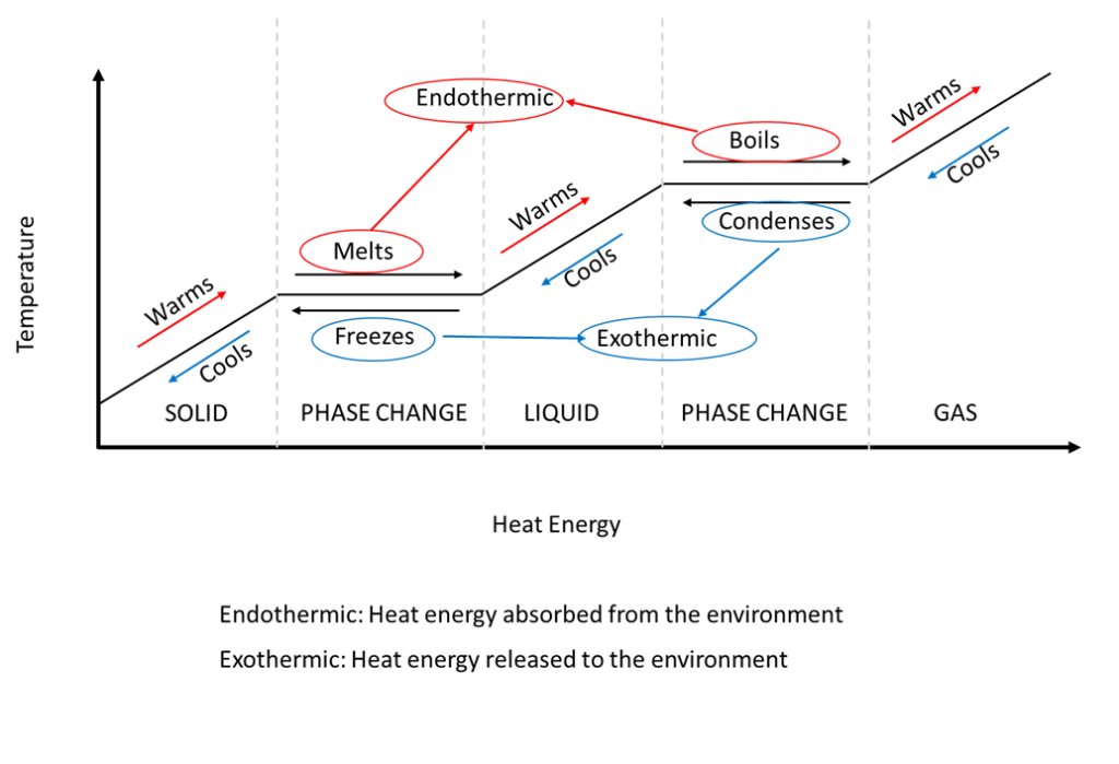
The relationship between the temperature of a medium versus the amount of heat energy added or removed from the environment is shown below.
The relationship between temperature and thermal energy of a system. Endothermic is heat energy absorbed from the environment. Exothermic is heat energy released to the environment.
It is important to note the flat portions of the graph labelled “Phase Change” are horizontal with respect to the temperature axis. This means that a significant amount of heat energy must be either added or removed from the surrounding environment in order to change a material from a solid to a liquid, or a liquid to a gas. This heat energy is sometimes referred to as latent heat.
Only once the material has completely changed its phase will the temperature continue to rise. Once the materials temperature starts to rise, the energy which is now added (or removed) from the system is called sensible heat, because a person could sense, or feel the difference in temperature.
Endothermic reactions such as melting or boiling take energy from the surrounding environment and use it to change the phase of the material in the cooling system.
Exothermic reactions such as freezing or condensing release energy from the system back into the environment.
Direct Expansion cooling systems use the boiling and condensing properties of a refrigerant to rapidly remove thermal energy from an area where it is undesirable, and dissipate it elsewhere.
Direct Expansion Air Conditioning Systems
34
Click play on the following audio player to listen along as you read this section.
Direct expansion, or DX cooling, uses the principles of thermodynamics to transfer heat from one area to another through the evaporation and condensation of a refrigerant, which serves as the medium through which heat is captured and removed from one area and released in another.
Air conditioners use this mechanism to move heat from inside a room to outside, meaning the air conditioning system must have a component installed inside the room or area to collect thermal energy, and another component outside the room to release that thermal energy to the environment.
Refrigerators and freezers use DX cooling to remove thermal energy from inside the freezer unit to the outside. They utilize the same components as an air conditioning system, though on a smaller scale and creating much colder temperatures.
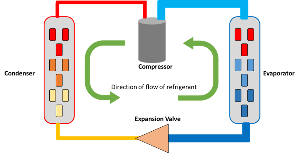
Components of direct expansion cooling system
There are four main components of any DX cooling system, plus a heat absorbent medium, often called the refrigerant, that regulate the transference of heat energy by creating the temperature and pressure differentials required for DX cooling:
The refrigerant, which is the medium that flows through the system, collecting and dissipating heat in different areas;
The compressor, which is an electrical motor load and supplies the energy to drive the refrigerant through the system;
The evaporator, which collects heat from the area, and facilitates the boiling of the refrigerant;
The condenser, which dissipates heat into the ambient environment by allowing the refrigerant to return to a liquid state;
The expansion valve, which acts as a regulator between the high and low pressure side of the system and allows for the drop in pressure and temperature necessary to facilitate DX cooling.
The whole system forms a closed loop, and is powered by the motor driven compressor. This device supplies the energy that drives the cooling system, and is usually a single-phase electrical motor load.
The compressor drives the next most critical component, the refrigerant, throughout the system. The refrigerant must have the property of boiling below room temperature. There are several varieties of refrigerant in use today, each with their own unique properties, but all share the common trait of evaporating at low temperatures. It is the property of changing phase, i.e. boiling, at low temperatures, that allows the refrigerant to maximize its ability to absorb thermal energy from a room or area.
The two components which facilitate the transfer of heat to or from the refrigerant are the evaporator located in the area to be cooled, and the condenser, located where heat may be dissipated, commonly outside of the building. The majority of the heat energy is dissipated in the condenser, and in order for heat transfer to occur, the air surrounding the condenser coil must be at a lower temperature than the refrigerant. This is why the compressor raises the temperature and pressure of the refrigerant, thus ensuring that there is sufficient heat gradient between the outside air and the refrigerant.
Between the condenser and the evaporator is the expansion valve, which regulates the pressure of the refrigerant. By allowing the refrigerant to expand, we increase the volume of space the gas can occupy, and thus lower the number of collisions that the atoms will have. This results in a lowering of kinetic thermal energy.
Since the expansion valve lowers the pressure of the gas by allowing it to expand into the larger volume of the intake pipe feeding the evaporator, the refrigerant experiences a decrease in temperature. This is how we can actively make something colder than room temperature.
Refrigerants are designed to have a boiling point low enough to evaporate and turn into a gas at room temperature. For heat to transfer there has to be a temperature difference between the room and the refrigerant. If the cold refrigerant now flows through the evaporator coils, and air blown across the evaporator coils is at a higher ambient temperature, the colder refrigerant will absorb the heat, or thermal energy from the air, which has the same effect as cooling that air.
By constantly cycling additional cold refrigerant through the room, heat can be steadily removed from the desired area, and dissipated outside the building.
The DX Cooling Cycle
35
Click play on the following audio player to listen along as you read this section.
A step-by-step analysis of the forces acting upon the refrigerant as it passes through each of the four main components of a DX cooling system will help in our understanding of the process.
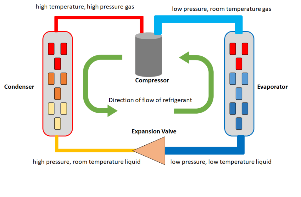
The conditions of the refrigerant at various stages of the DX cooling cycle.
The Compressor
This is the component which drives the refrigerant throughout the system. It receives a low pressure, room temperature gas, and pumps the refrigerant through a valve into a much narrower diameter pipe and this restriction in volume, combined with the increased pressure of the refrigerant causes its temperature to rise rapidly. The refrigerant is a high temperature, high pressure gas as it is exiting the compressor valve.
The Condenser
As the refrigerant enters the condensercoil it is a high temperature, high pressure gas. The condenser coil has a large surface area that is exposed to the air. It will often be attached to a large metal grill to increase its available surface area, dissipating heat through conduction as well as convection. The refrigerant dissipates the thermal energy and condenses into a liquid as it moves through the coil. Most of the heat energy is dissipated at this stage, utilizing the Second Law of Thermodynamics to transfer heat from the refrigerant to the surrounding air. A fan can be incorporated into the cooling system to help circulate air across the condenser coils and take heat away from the system. Condenser units are often installed outdoors on rooftops for convenient heat dissipation.
The Expansion Valve
This component regulates the flow of refrigerant from the high pressure/temperature side of the system and the low pressure/temperature side. As the refrigerant enters the expansion valve it is a high pressure, room temperature liquid, and as it expands into the larger area beyond the valve, its pressure, and thus its temperature drops dramatically. This is when the refrigerant is at its coldest, as a low pressure, low temperature liquid. The amount of refrigerant that the valve lets through is controlled by a diaphragm, which is connected to a capillary type thermal sensor filled with a separate refrigerant. The sensing bulb is attached to the exit line of the evaporator. By sensing the temperature of the refrigerant as it leaves the evaporator, the expansion valve can let in more or less refrigerant at a given moment, thus raising or lowering the temperature of the refrigerant as it enters the evaporator.
The Evaporator
The evaporator coils are similar in design to the condenser coils but with the purpose of drawing heat from the surrounding air into the refrigerant. Again a large surface area helps to conduct heat from the air to the refrigerant. Fans can be used circulate the air and replace cooled air with warmer air. As the low pressure, low temperature liquid enters the evaporator coil and starts to absorb heat, it rapidly evaporates from a liquid to a gas. This phase shift draws energy from the surrounding air in the form of heat, and carries it away as the low pressure, room temperature gas is suctioned towards the compressor, where energy is added to drive the cycle again.
Self Test 4
36
Take the following self test as many times as you like.
If using the print, PDF, or eBook copy of this book, navigate to the above link to complete the quiz. However, the quiz questions are also provided at the end of the book for offline use: Offline Copies of Chapter Quizzes.
Glossary
1
Offline Copies of Chapter Quizzes
2
Electrical Terms and Definitions – Self Test 1
Questions
Unless specifically marked, the total connected electrical load shall not exceed _____ of the rating of the circuit’s overcurrent device.
75%
80%
100%
125%
Household heating and cooling equipment is supplied by which style of voltage?
Single-phase
Three-phase
Double-phase
Opposing-phase
An overload is a:
Sharp fast rise in current values above rated levels.
A slow, prolonged rise in current values above rated levels.
A decrease in current values below rated levels.
An immediate drop in current values to zero.
An overcurrent is a:
Sharp fast rise in current values far above rated levels.
A slow rise in current values above rated levels.
A decrease in current values below rated levels.
An immediate drop in current values to zero.
Low-voltage-release is a term that describes a:
Circuit that will automatically reenergize after return of power following a power outage.
Circuit that will not automatically reenergize after return of power following a power outage.
Circuit that will remain energized despite a power outage.
Circuit that will automatically open the contacts of an overcurrent device upon loss of power.
Low-voltage-protection is a term that describes a:
Circuit that will automatically reenergize after return of power following a power outage.
Circuit that will not automatically reenergize after return of power following a power outage.
Circuit that will remain energized despite a power outage.
Circuit that will automatically open the contacts of an overcurrent device upon loss of power.
Low-voltage-release is provided by circuits known as:
2-wire circuits
3-wire circuits
4-wire circuits
Single-wire circuits
Low-voltage-protection is provided by circuits known as:
2-wire circuits
3-wire circuits
4-wire circuits
Single-wire circuits
Answers
B
A
B
A
A
B
A
B
Heating – Self Test 2
Questions
When an electric heating load is inadvertently connected at half its rated voltage, the power dissipated is:
Four times the rated power
Twice the rated power
One quarter the rated power
When an electric heating load is inadvertently connected at twice its rated voltage, the power dissipated is
Four times the rated power
Twice the rated power
Half the rated power
One quarter the rated power
Is it acceptable to install electrical receptacles directly above baseboard heaters?
Yes, always.
No, never.
Occasionally, as long as they look nice.
Yes, only with GFCI protection.
When a fireplace uses a self-generating 750 millivolt system, what device is used to supply the power for the gas valve?
A thermopile
A thermocouple
A solenoid
A bimetallic switch
What is the purpose of the heat exchanger in a gas-fired furnace?
To separate the heated air from the cold air return
To separate heated air from the air flow to the rooms
To separate the products of combustion from the gas valve
To separate the products of combustion from the heated air
Where must the automatic thermostatic control be when baseboard heaters are used to heat a dwelling unit?
on each branch circuit
on each individual unit
in each overcurrent device
in each room or heated area
A thermocouple is generally thought of as:
A voltage device
An impedance device
A current device
A resistance device
In floor heating cables are designed to provide enough heat to do what?
Heat the room or area
Reduce the heating demand of baseboard heaters
Reduce the heating demand of the furnace
Eliminate cold floors
Some heating equipment will have a high-temperature-limit switch. What is the purpose of this switch?
To protect against low temperature level
To set the temperature of the water
To prevent temperature from exceeding a safe value
To regulate gas flow
When a stronger signal than a thermocouple is required, a thermopile can be used. How are thermocouples connected to make a thermopile?
In series-aiding
3-wire
In series-opposing
In parallel
Why is a thermocouple used in conjunction with a pilot light in a gas fired furnace?
To ensure immediate ignition of gas with the opening of the main gas valve
To re-ignite the pilot flam should it be extinguished
To hold open the pilot-flame valve while it is lit, and automatically close it if the pilot-flame is extinguished
To prevent the pilot-flame valve from closing if the flam is extinguished
A thermostat is considered a:
Temperature activated switch
Liquid-level switch
Position sensing switch
Pressure switch
A programable thermostat combines the features of which two devices?
An electronic timer and a thermostat
A thermostat and an anticipator resistor
An electronic timer and a load
An electronic timer and an anticipator resistor
A low-voltage thermostat used to control a central gas fired furnace will incorporate an _____________ to prevent overshoot of desired room temperature.
Anticipator resistor
Normally open contact
Normally closed contact
An electronic timer
A 240-volt line-voltage thermostat used to control the household heating apparatus, when in the marked “off” position, it must disconnect?
The grounded conductor only
Two ungrounded conductors
One ungrounded conductor
The grounding conductor only
A 240-volt line-voltage thermostat used to control the household heating apparatus, when in the marked “min” position, it must disconnect?
The grounded conductor only
Two ungrounded conductors
One ungrounded conductor
The grounding conductor only
If extra low voltage relays and thermostats are used to control heating equipment, which one of the following is not a valid reason for their use?
Reduce voltage ratings of control conductors
To reduce the equipment cost
To decrease the control circuit current draw
To increase the heating capacity
If a baseboard thermostat has a rating of 20 amps at 250 volts, what is the maximum wattage heating unit that it can control?
2,500 W
1,000 W
1,500 W
5,000 W
Answers
C
A
B
A
D
A
D
C
A
C
A
A
A
B
C
D
D
Ventilation – Self Test 3
Questions
In order to maintain healthy air levels in a building, a certain amount of ___________ is mixed in with the treated air.
Fresh air
Carbon-dioxide
Products of combustion
Reverse air flow
The term “static pressure” when applied to ventilation refers to:
Maximum pressure the air-handling unit can handle
The force exerted by a moving air stream
The outward force of the air in the ducting system
The resistance to the flow of air in a ducting system
The term “velocity pressure” when applied to ventilation refers to:
Maximum pressure the air-handling unit can handle
The force exerted by a moving air stream
The outward force of the air in the ducting system
The resistance to the flow of air in a ducting system
The term “total pressure” when applied to ventilation refers to:
Maximum pressure the air-handling unit can handle
The force exerted by a moving air stream
The outward force of the air in the ducting system
The resistance to the flow of air in a ducting system
Axial fans have outgoing air flow that is _____________ to the air intake
Parallel
Perpendicular
Inverted
Oblique
Centrifugal fans have outgoing air flow that is _____________ to the air intake.
Parallel
Perpendicular
Inverted
Oblique
Axial fans are often employed to:
Move air through an HVAC system
Move air over the condenser coils of air-conditioning systems
Prevent air from moving in a certain direction
Recirculate air in a room
Centrifugal fans are often employed to:
Move air through an HVAC system
Move air over the condenser coils of air-conditioning systems
Recirculate air in a room
Prevent air from moving in a certain direction
Dampers are devices installed in the duct work of buildings to
Help regulate the flow of air through a duct system
Drive air from heated to non-heated areas
Prevent the mixing of fresh air from outside the building
Monitor the flow of air through a duct system
Answers
A
C
B
D
A
B
B
A
A
Mechanical Cooling – Self Test 4
Questions
A heat pump can also be used to cool the building when the outside air temperature is warm. How is this achieved?
The direction of flow of the air is reversed
The direction of flow of the refrigerant is reversed
The direction of flow of the current is reversed
The direction of rotation of the motor is reversed
When using DX cooling, which device is responsible for capturing heat from whatever place or medium needs to be cooled?
Condenser
Refrigerant
Evaporator
Compressor
When using DX cooling, which device is responsible for releasing heat from whatever place or medium needs to be cooled?
Condenser
Refrigerant
Evaporator
Compressor
When using DX cooling, what is responsible for transferring thermal energy from whatever place or medium needs to be cooled?
Condenser
Refrigerant
Evaporator
Compressor
When using DX cooling, which device is responsible for driving the refrigerant from whatever place or medium needs to be cooled?
Condenser
Refrigerant
Evaporator
Compressor
What process does mechanical refrigeration rely on to work?
Evaporation
Conduction
Convection
Radiation
What name is given to the method of removing energy in the form of heat from an object?
Conduction
Convection
Refrigeration
Radiation
What do air-cooled condensers use to circulate air across the condensing coil?
Exhaust system
Ambient evaporation
A chiller pump
A motor-driven fan
What is used by a hydronic system that allows it to be used for both the heating and cooling of a home?
A draft regulator
Hydraulic fluid
Pneumatic air
Fluid, such as water
Thermal energy is _____________ by a DX cooling system
Created
Destroyed
Transferred
Eliminated
Thermal energy flows spontaneously from areas of ____________ to areas of _____________.
Higher temperature, lower temperature
Lower temperature, higher temperature
Ambient temperature, lower temperature
Higher temperature, ambient temperature
An exothermic reaction ______________ thermal energy from the surrounding environment
Releases
Absorbs
Creates
Destroys
An endothermic reaction ______________ thermal energy from the surrounding environment.
Releases
Absorbs
Creates
Destroys
Answers
B
C
A
B
D
A
C
D
D
C
A
A
B
Versioning History
3
This page provides a record of edits and changes made to this book since its initial publication in the B.C. Open Textbook Collection. Whenever edits or updates are made in the text, we provide a record and description of those changes here. If the change is minor, the version number increases by 0.01. If the edits involve substantial updates, the version number increases to the next full number.
The files posted by this book always reflect the most recent version. If you find an error in this book, please fill out the Report an Open Textbook Error form.