When you have completed this module, you will be able to:
- Describe an assembly and explain the difference between a top-down and a bottom-up assembly.
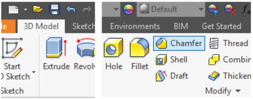
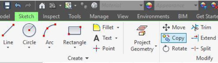
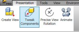
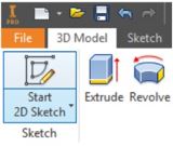
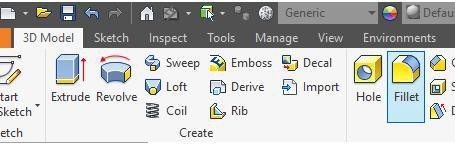
- Describe and apply the SLICE GRAPHICS command.
- Describe the PLACE COMPONENT and PLACE CONSTRAINT commands and apply them to assemble a series of parts to create an assembled model.
An Assembly File
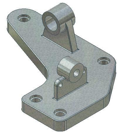
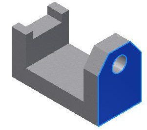
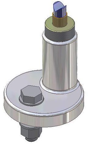
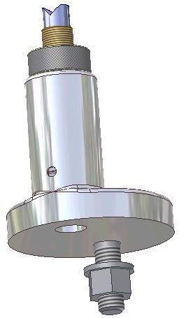
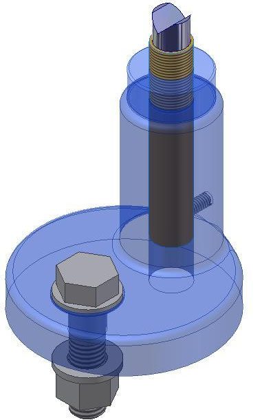
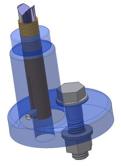
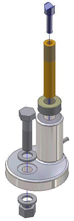
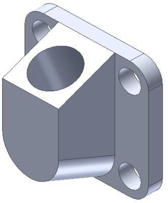
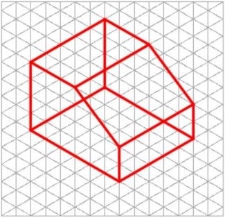
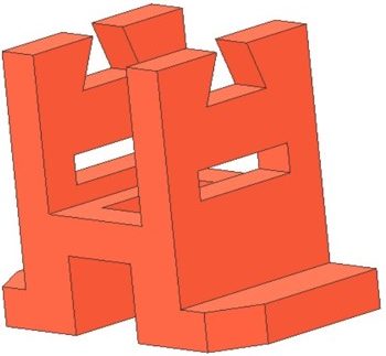
An assembly file contains the information required to assemble two or more part files to create an assembled model. See Figure 22-1. As the model is assembled, assembly constraints must be assigned so that each part knows how it aligns or fits with the other parts in the assembled model. A part (.ipt) file that has been placed in the assembly can be edited while in the assembly file and the modifications will be saved back to the original part file. On the other hand, if the original part file is modified after the assembly file has being created, the modifications will automatically display in the assembly. An assembly file does not actually contain any of the part files that are placed in the file, it simply contains a reference to them.
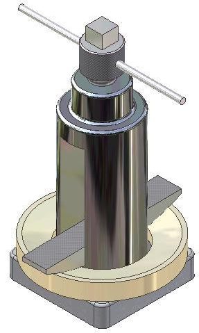
Figure 22-1
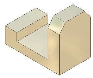
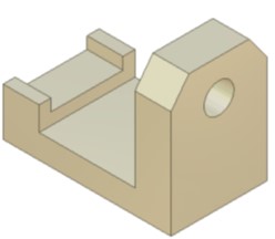
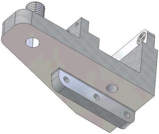
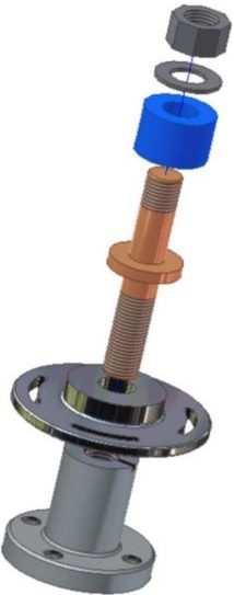
An Assembled Model
A reference is a link back to the part files. The part files that have been placed in an assembly file must be available to Inventor to display them when an assembly file is opened. The current project file keeps track of those links and will automatically keep track of the location of all the part files. If an assembly file is sent to a client or an associate, the part files that were placed in the assembly file must also be included.
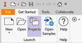
Creating an Assembly File
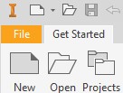
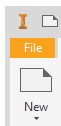
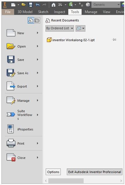
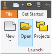
To create an assembly file, use the NEW command and select an assembly template rather than a part template. An assembly file has the extension .iam. IAM is an acronym for Inventor Assembly.
MUST KNOW: An assembly file contains the information required to assemble two or more part files to create the assembled model. An assembly file has the file extension .iam. IAM is an acronym for Inventor Assembly.
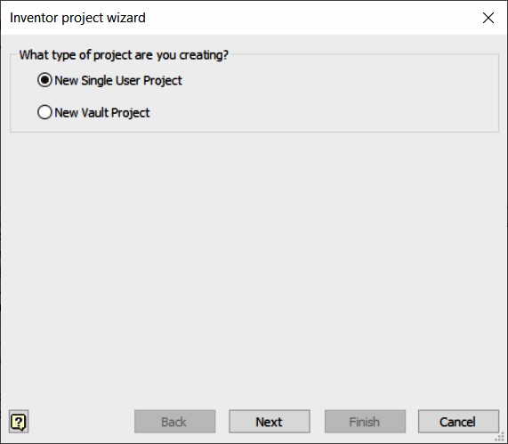
Bottom-up vs Top-down
Assembly files can be created using either the bottom-up or the top-down method. A bottom-up assembly is an assembly created from a series of part files that were previously created and saved in their own .ipt file. A top-down assembly is an assembly file where all parts of the assembly are created on the fly. In other word, they are created in the active assembly file, one at a time. They are aligned and constrained in their correct position in relationship to the other parts in the assembled model. Inventor will save each part in its own file with the extension .ipt. In the Inventor book, only the bottom-up method is taught.
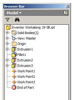
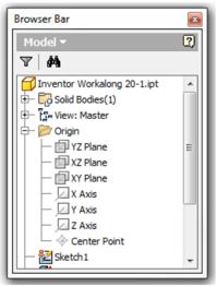
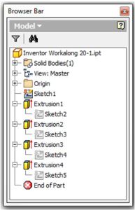
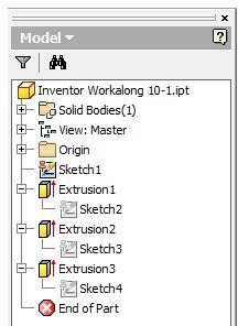
The Browser Bar in an Assembly
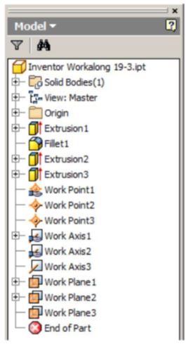
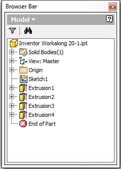
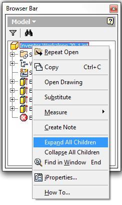
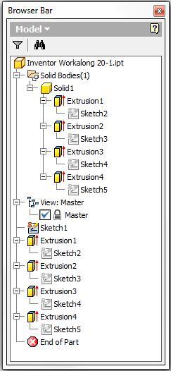
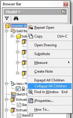
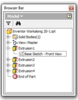
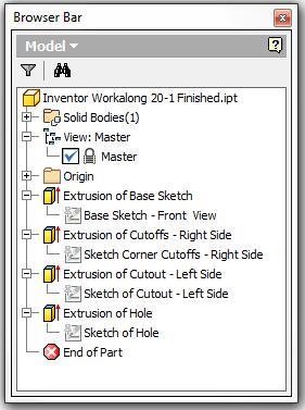
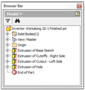
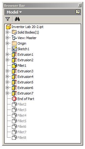
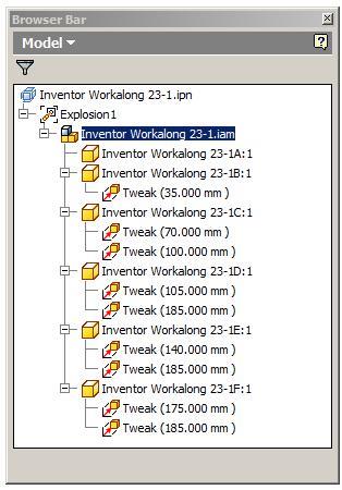
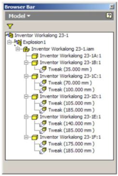
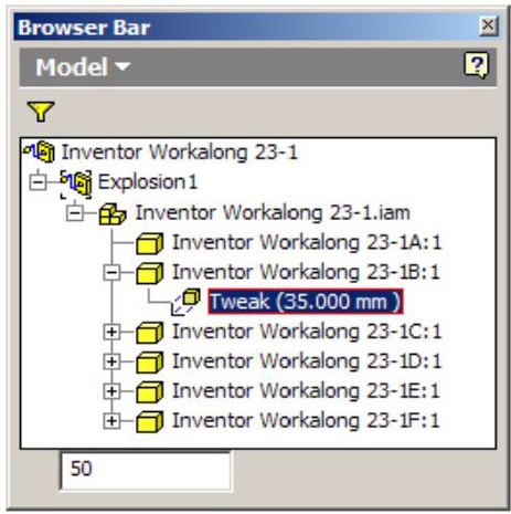
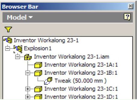
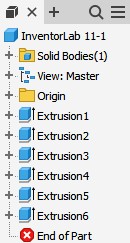
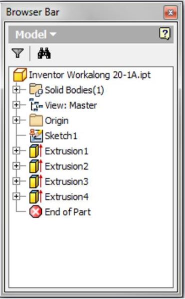
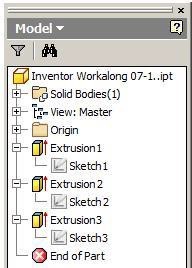
When an assembly is the active file, the Browser bar will display all of the parts that have been placed in the assembly. If a part in the browser is expanded it will display its children which includes its alignment and constraints to the other parts of the assembled model. See Figure 22-2.
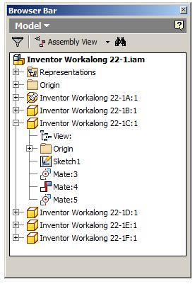
Figure 22-2
An Assemble in
the Browser Bar
Inventor
If the same part is placed more then once into the assembly file, the Browser bar will number them accordingly. For example, this may happen if an assembly required two identical bolts. Only one part file is created and named Bolt.ipt. It is then placed into the assembly file twice. The Browser bar would number the bolts parts as follows:
On the first occurrence: Bolt:1
On the second occurrence: Bolt:2
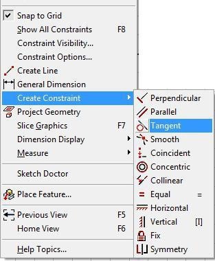
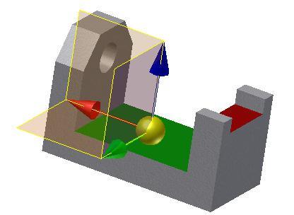
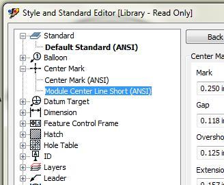
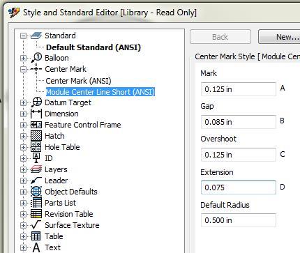
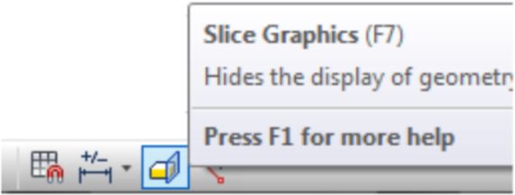
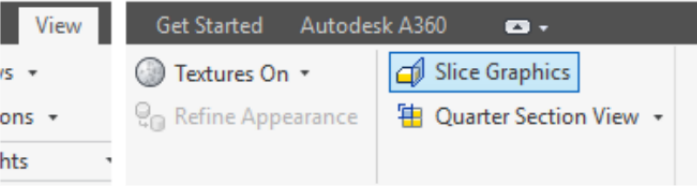
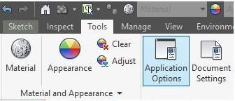
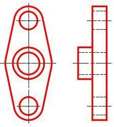
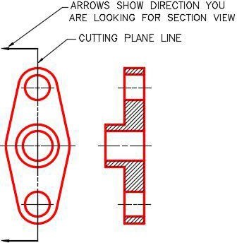
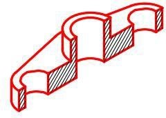
The SLICE GRAPHICS command is used to slice away the model on the active sketching plane temporarily removing all of the material in front of the sketching plane. The sketching plane must be active before using this command.Shortcut: F7
WORK ALONG: Creating the Parts for an Assembly
Step 1
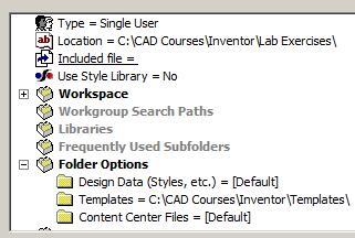
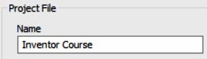
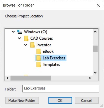
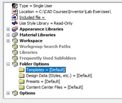
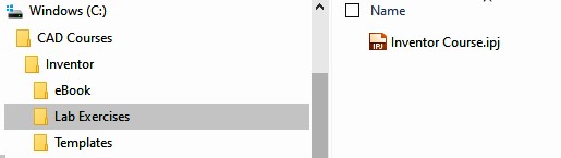
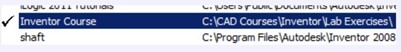
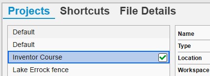
Check the default project and if necessary, set it to Inventor Course.
Step 2
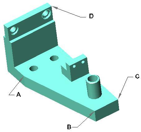
Use the following instructions to complete all parts in this workalong. Create the following parts and ensure that you do the following:
A Each part must be saved in its own .ipt file.
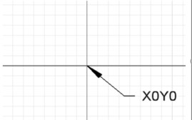
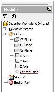
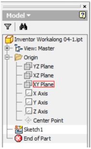
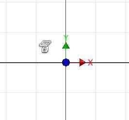
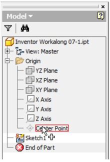
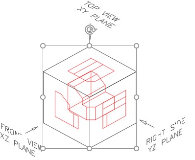
B Project the Center Point onto the Base sketch plane and note the location of X0Y0Z0.
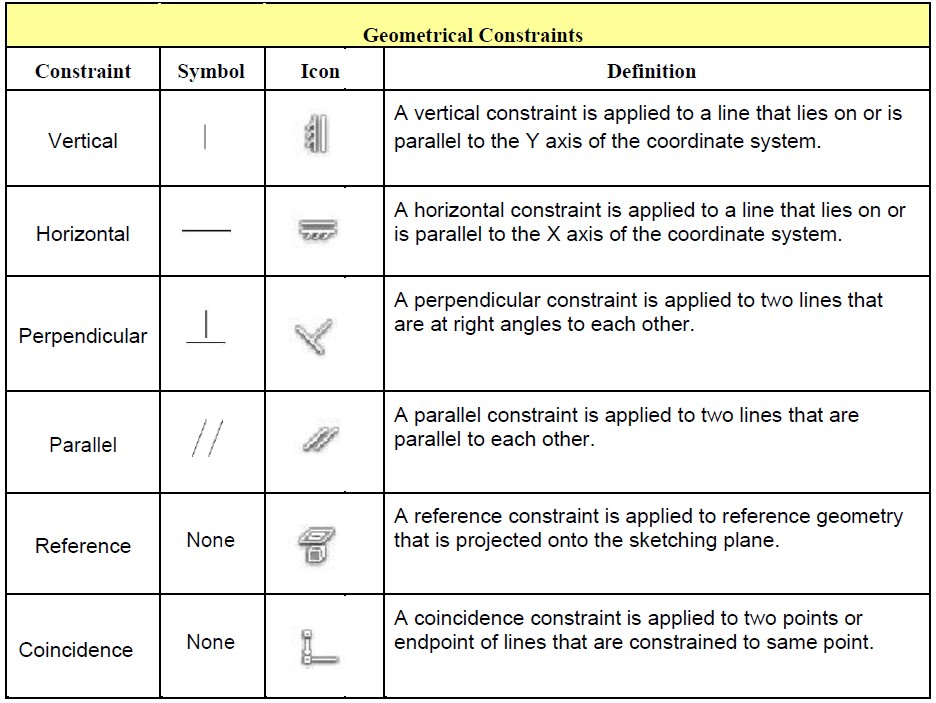
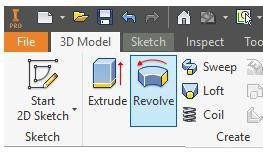
C Draw the necessary sketches and extrude or revolve them to produce the solid model shown. Apply all of the necessary geometrical and dimensional constraints to fully constrain each sketch.
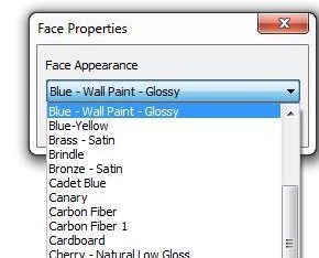
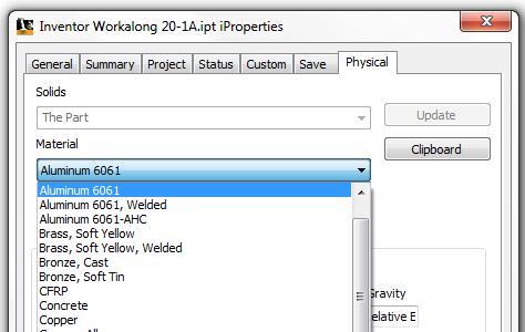
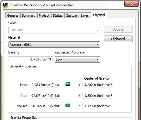
D Apply the colour and material shown.
Step 3
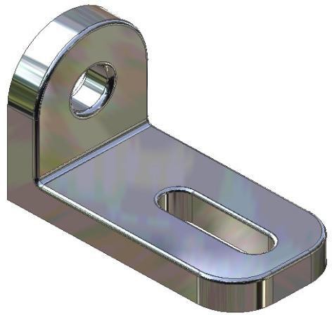
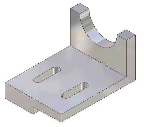
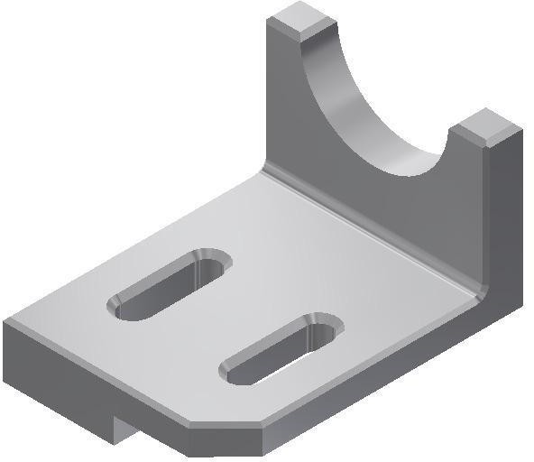
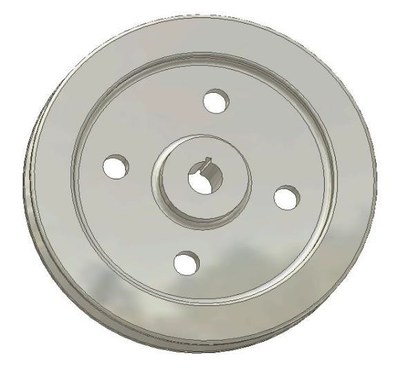
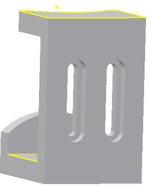
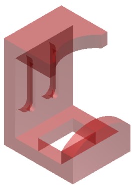
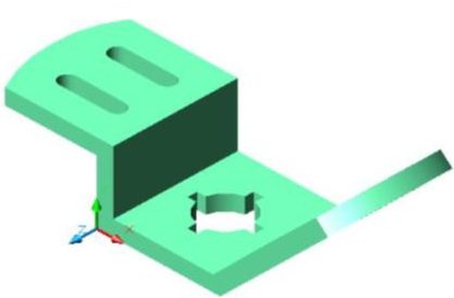
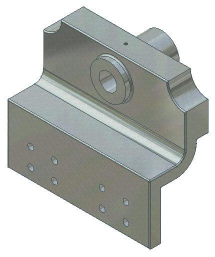
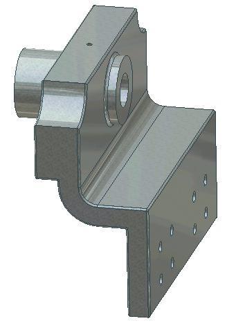
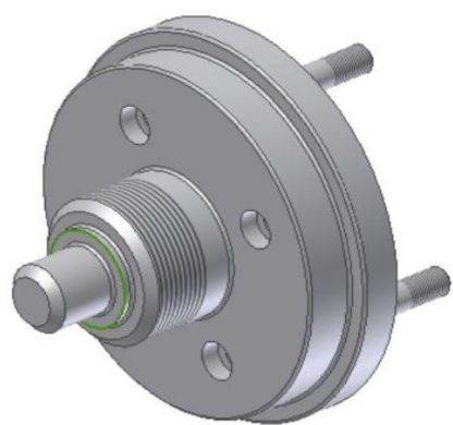
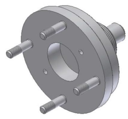
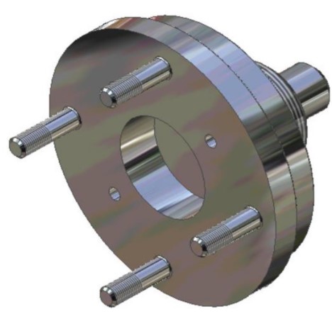
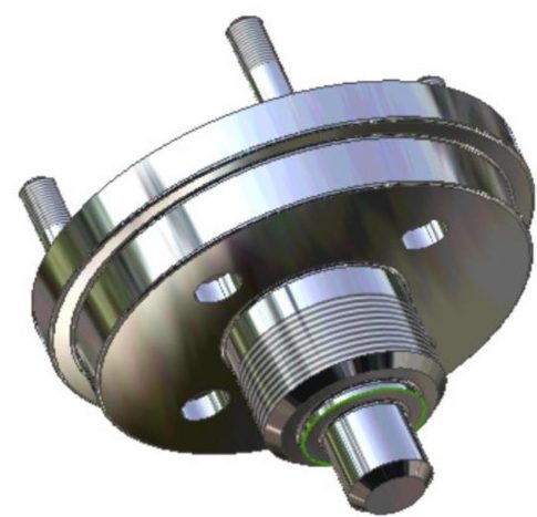
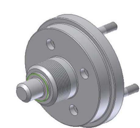
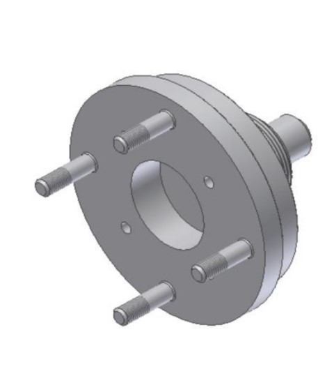
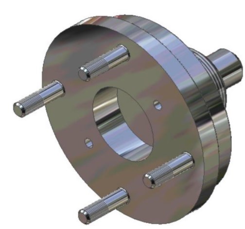
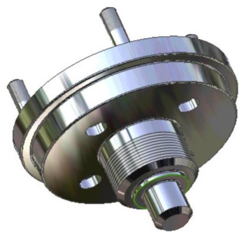
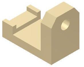
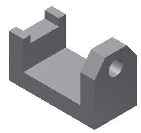
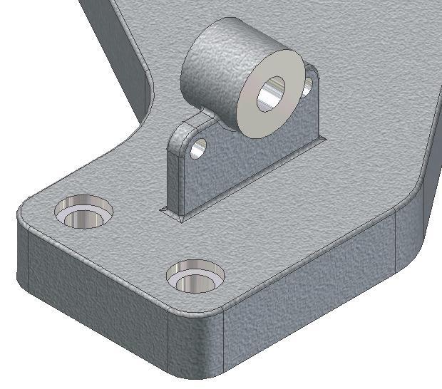
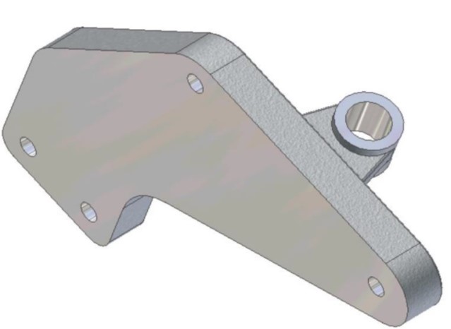
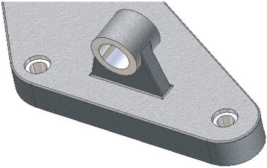
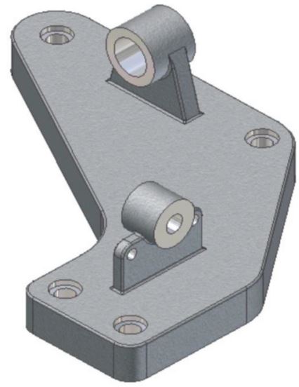
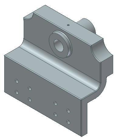
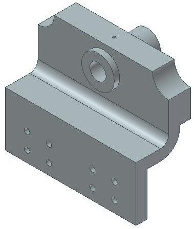
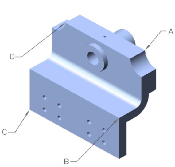
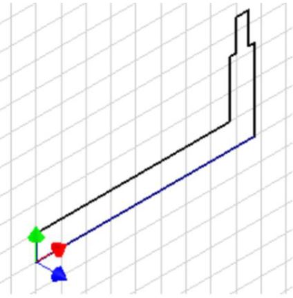
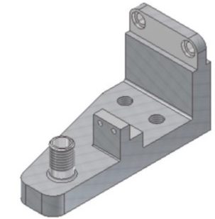
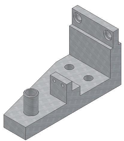
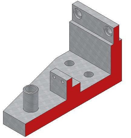
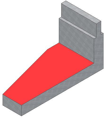
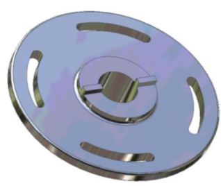
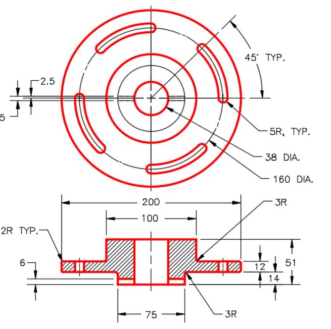
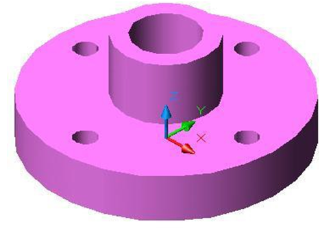
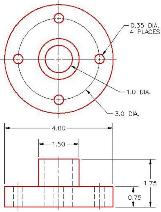
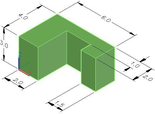
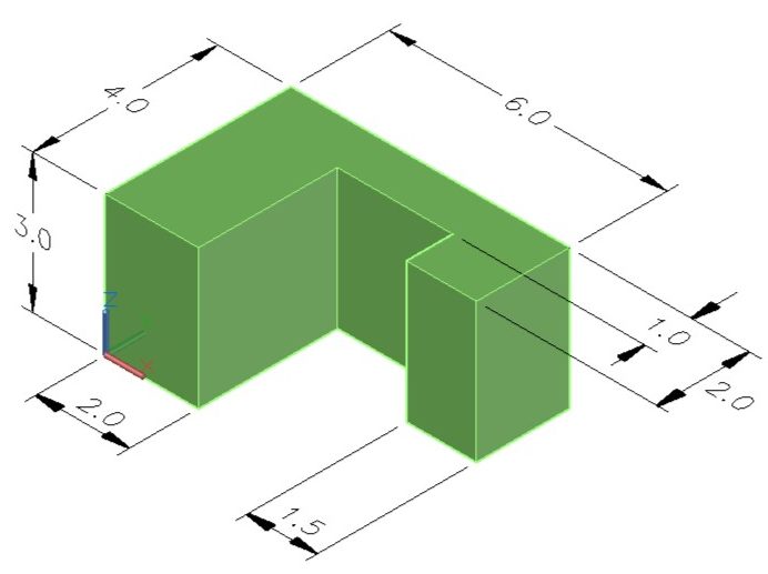
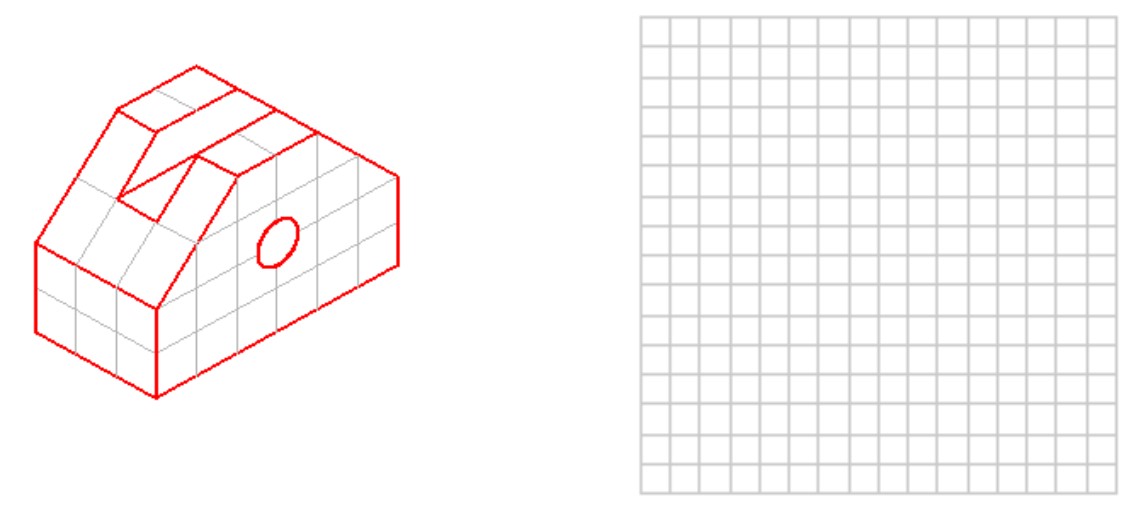
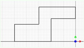
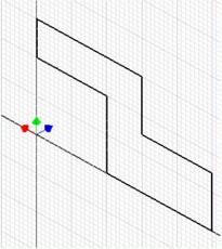
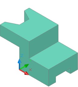
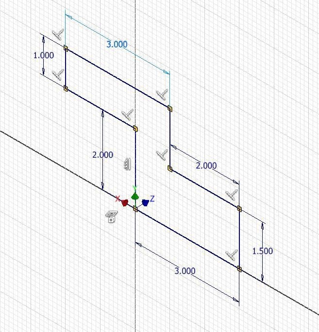
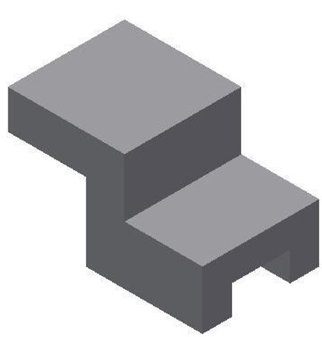
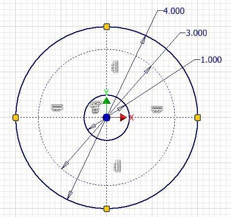
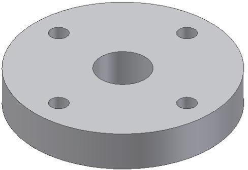
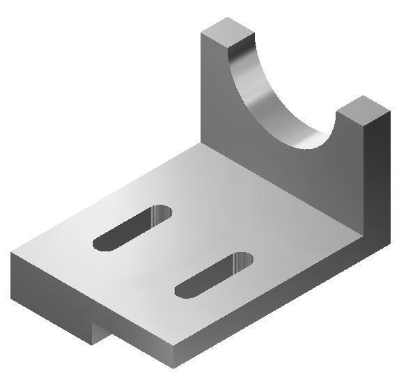
Construct Part A. (Figure Step 3A, 3B, and 3C)
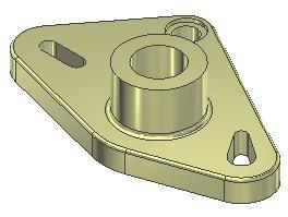
Part: Base
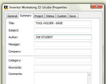
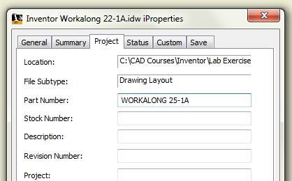
Part Name: Inventor Workalong 22-1A
Template: English-Modules Part (in).ipt
Color: Stainless – Brushed
Material: Stainless Steel
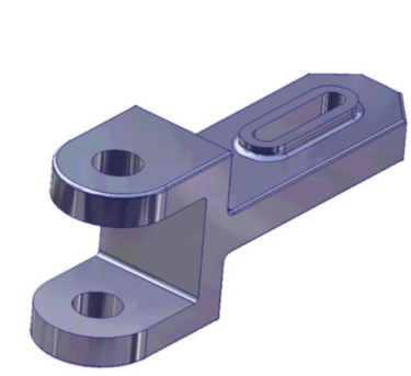
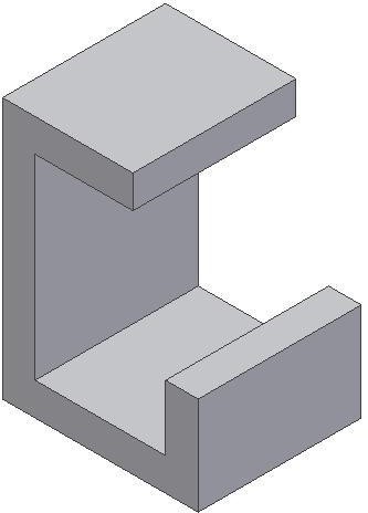
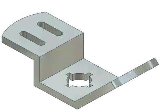
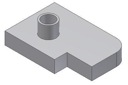
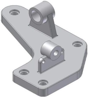
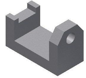
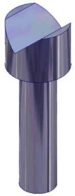
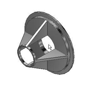
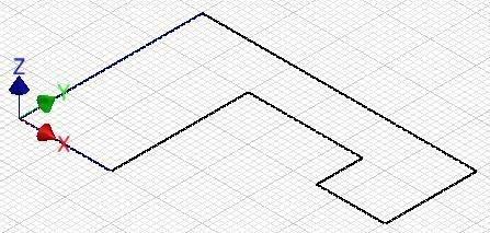
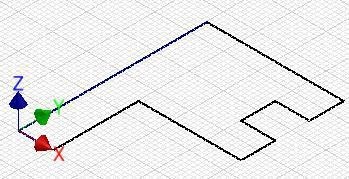
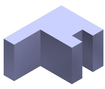
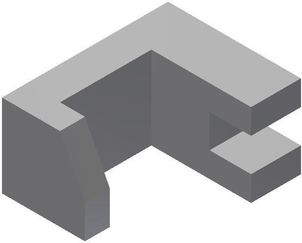
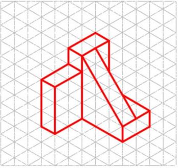
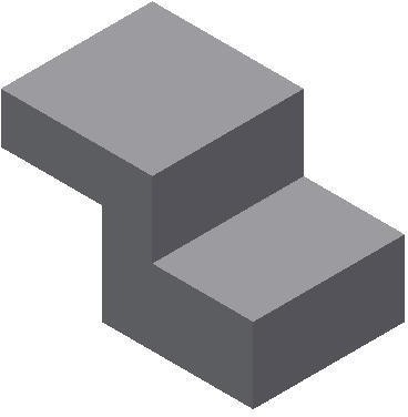
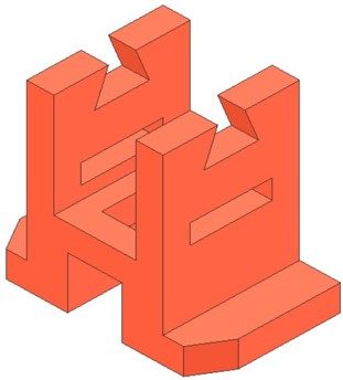
Figure Step 3A
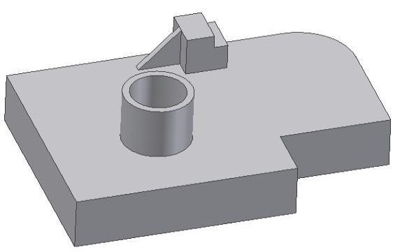
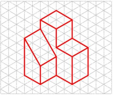
Solid Model – Home View
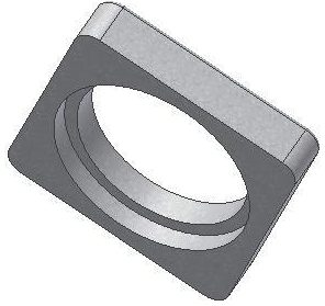
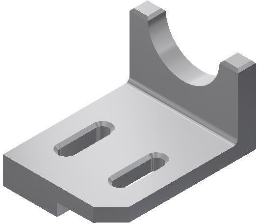
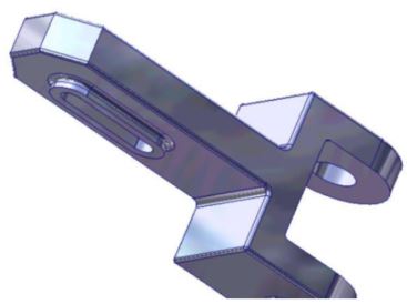
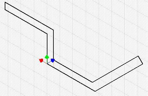
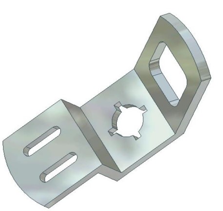
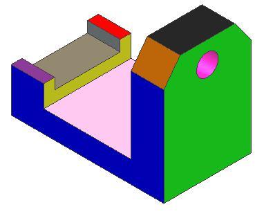
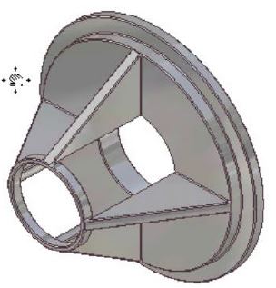
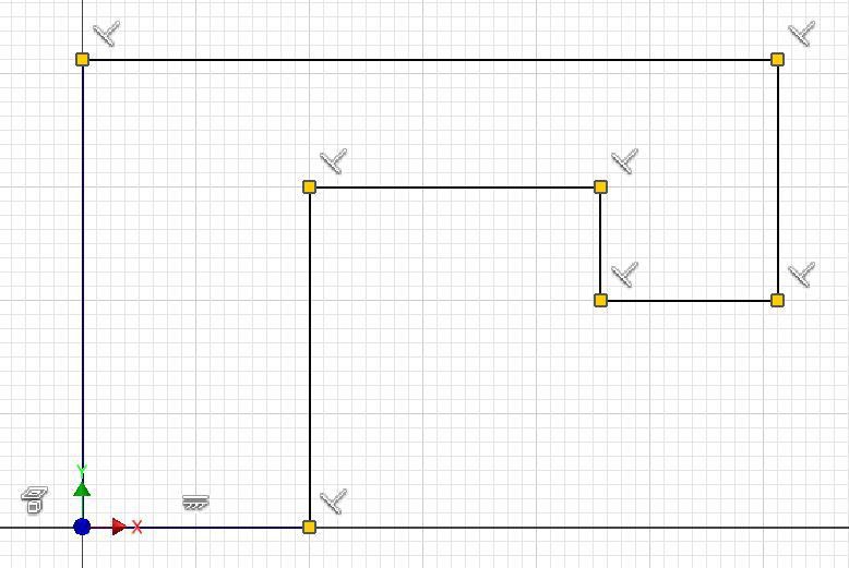
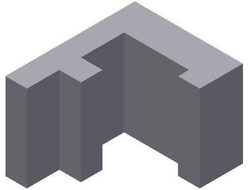
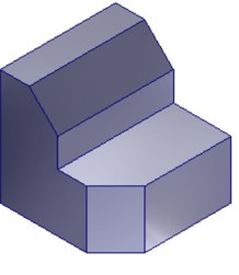
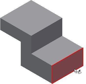
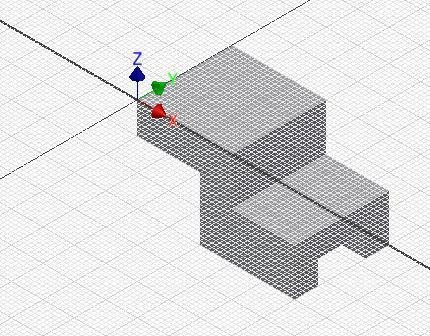
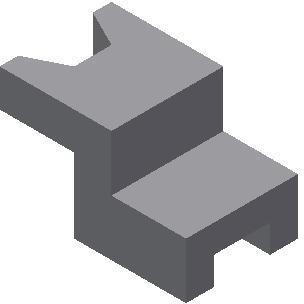
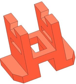
Figure Step 3B
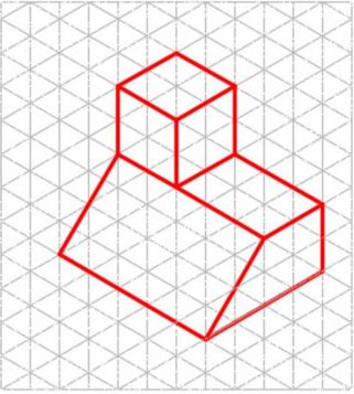
Solid Model – Orbited View
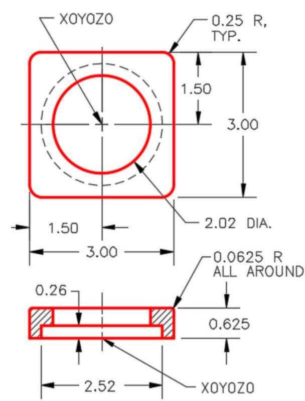
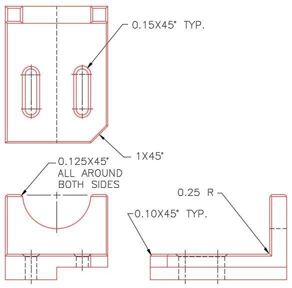
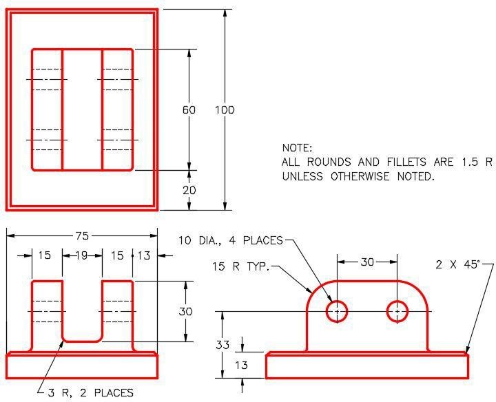
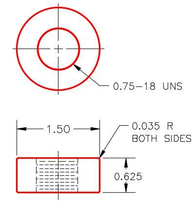
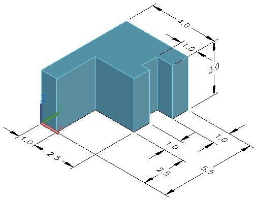
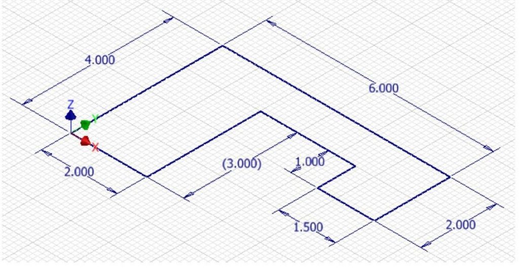
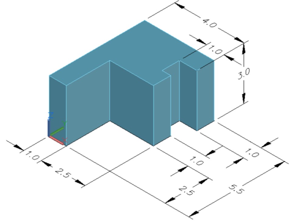
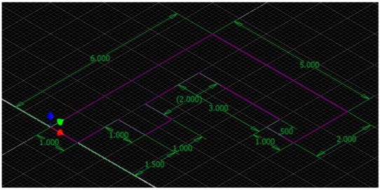
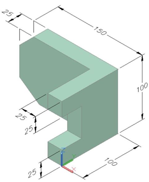
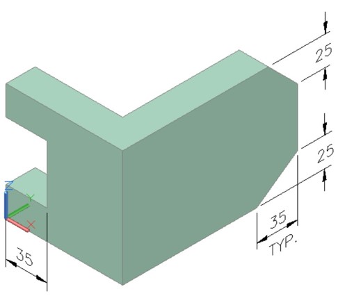
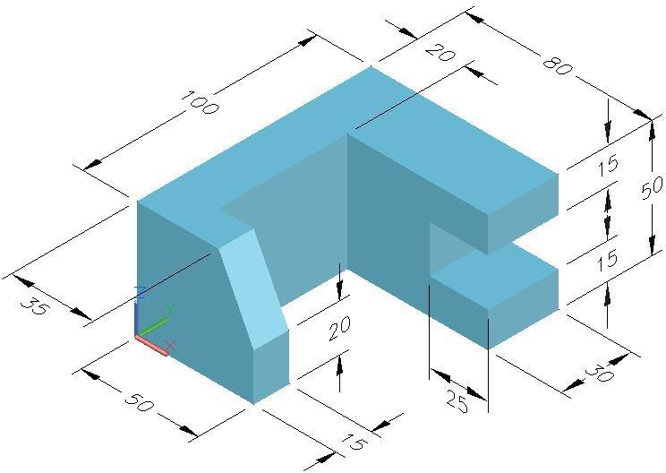
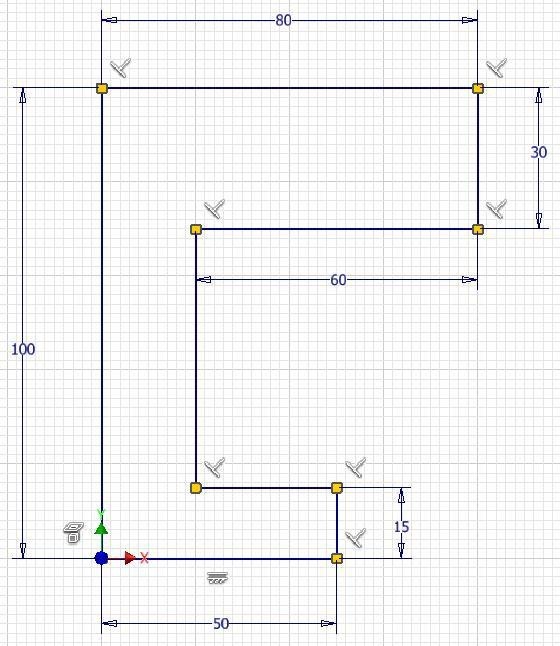
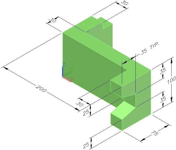
Figure Step 3C
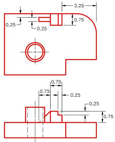
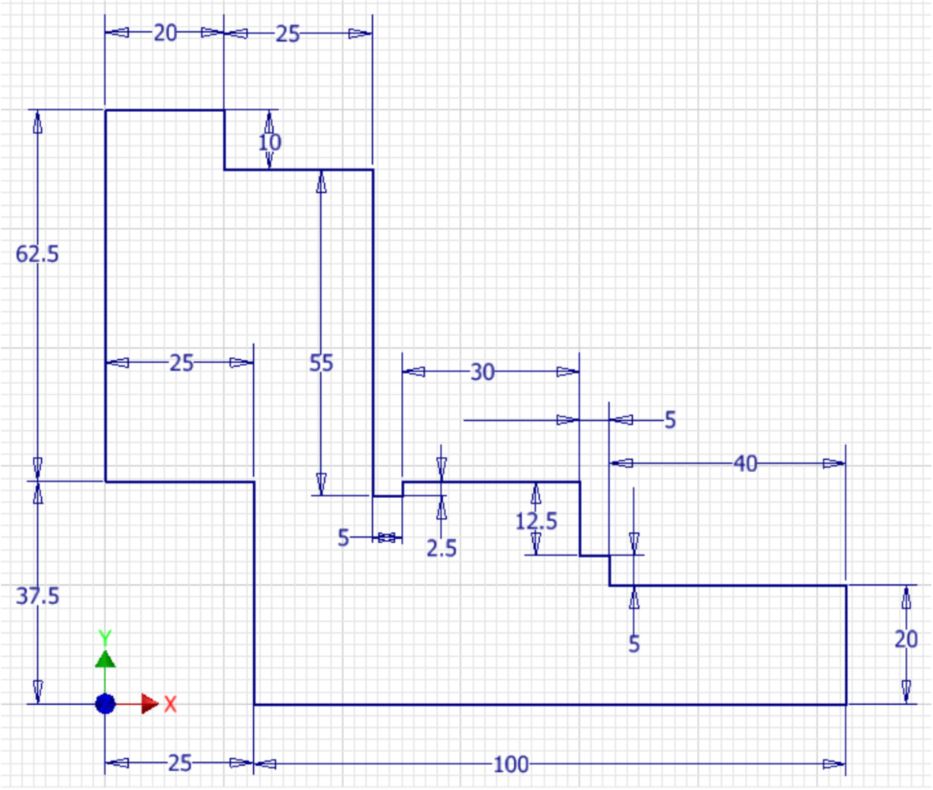
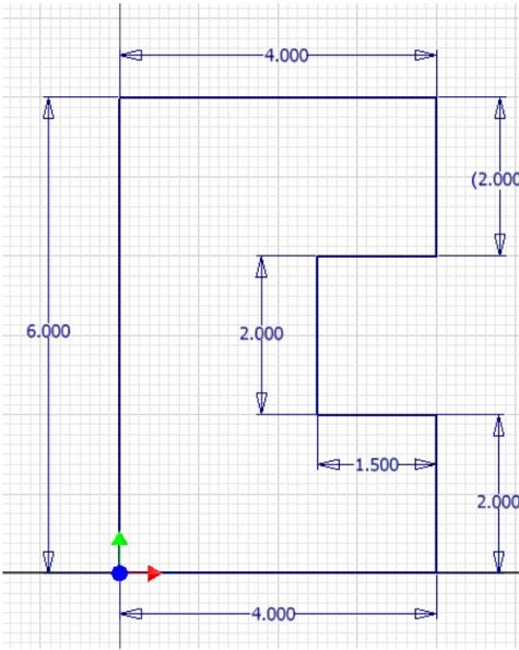
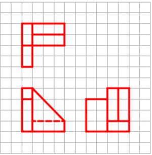
Dimensioned Multiview Drawing [Click to see image full size]
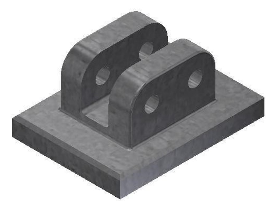
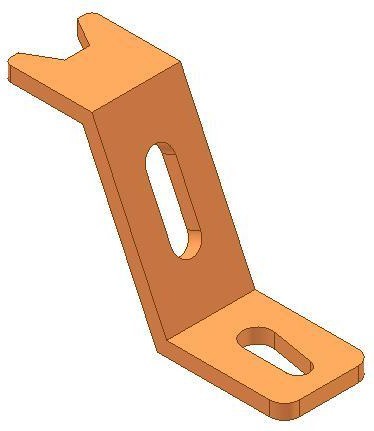
Step 4
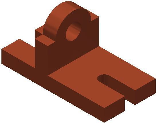
Construct Part B. (Figure Step 4A and 4B)
Note: See Steps 3 to 14 if you require help creating this model.
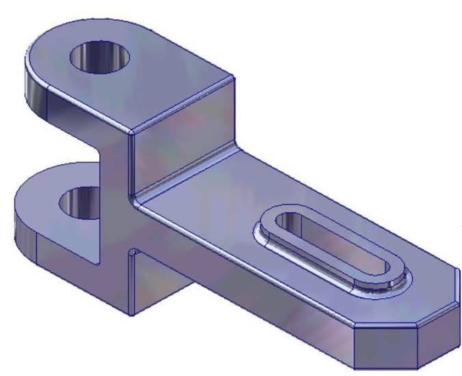
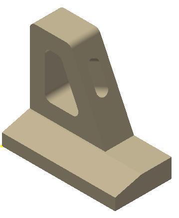
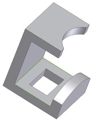
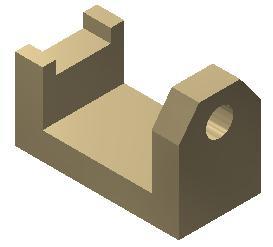
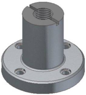
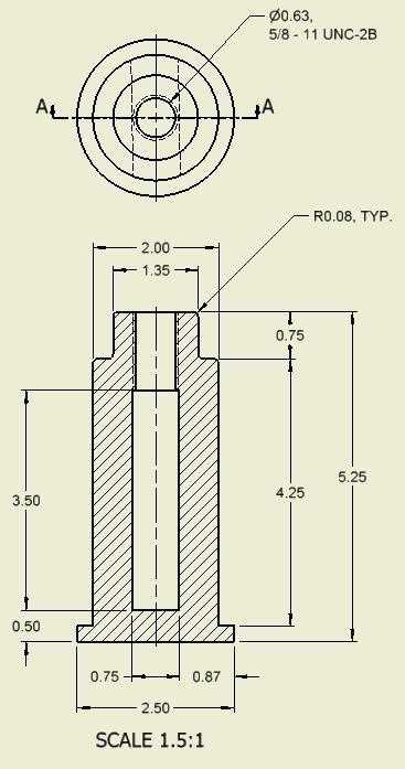
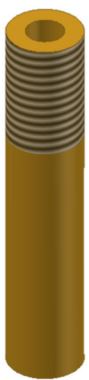
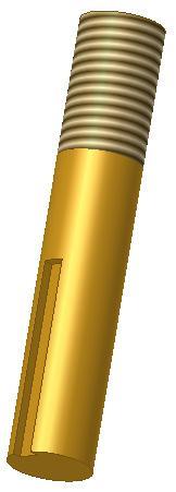
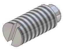
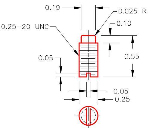
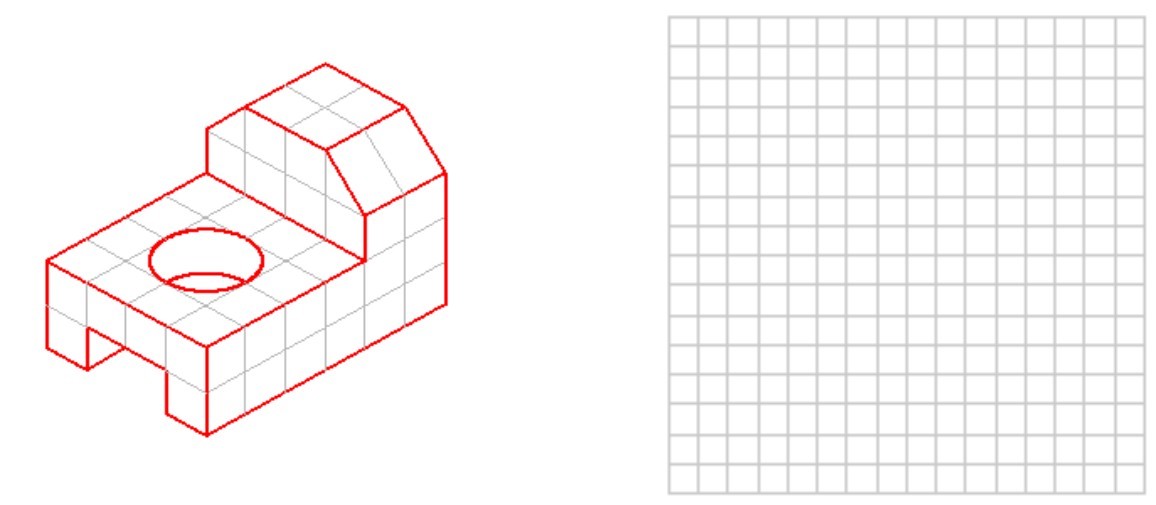
Part: Post
Part Name: Inventor Workalong 22-1B
Template: English-Modules Part (in).ipt
Color: Chrome – Black Polished
Material: Steel
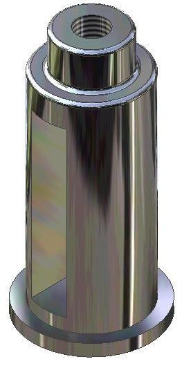
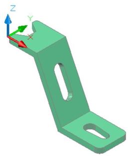
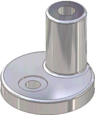
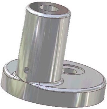
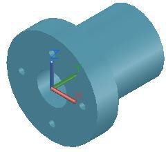
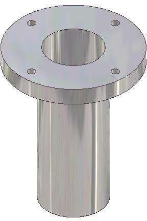
Figure Step 4A
Solid Model –
Home View
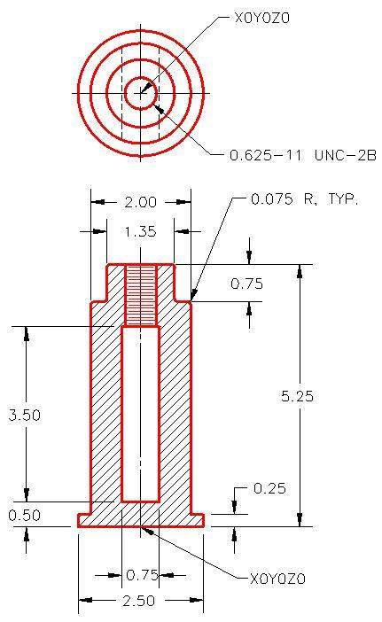
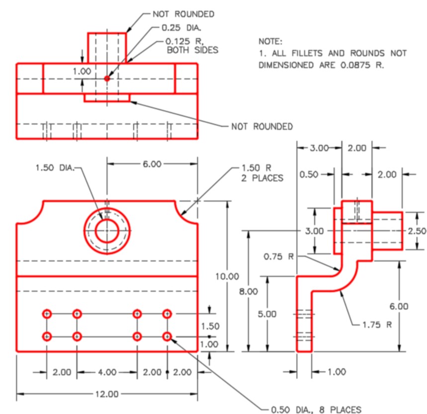
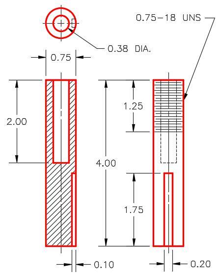
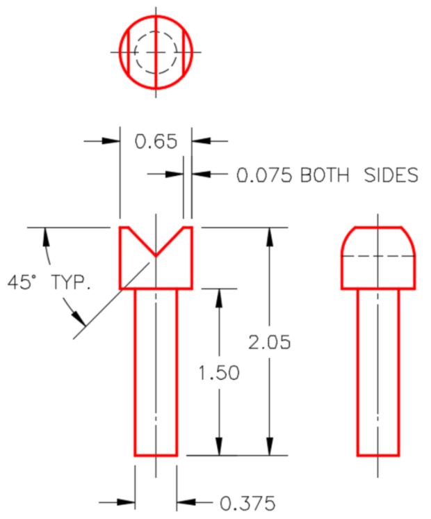
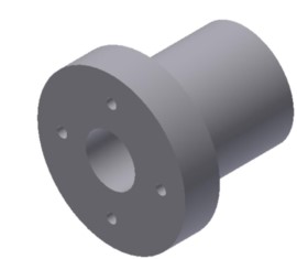
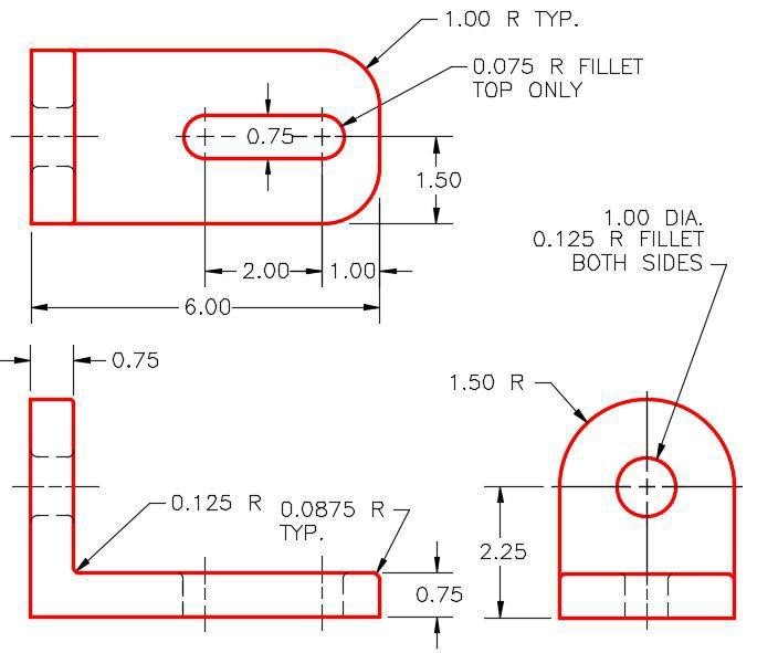
Figure Step 4B
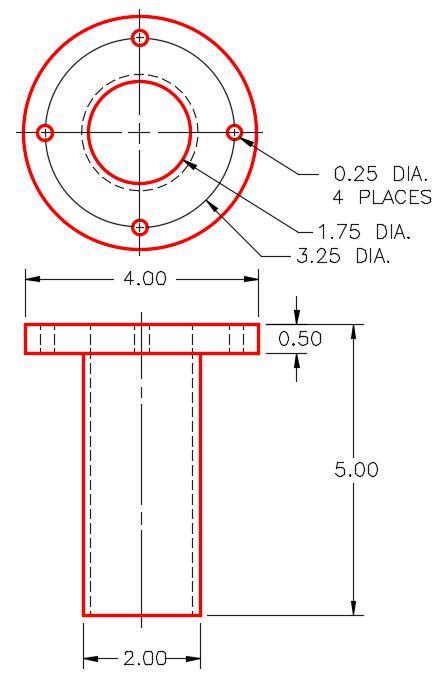
Dimensioned Multiview Drawing
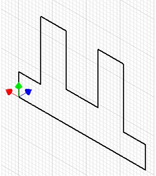
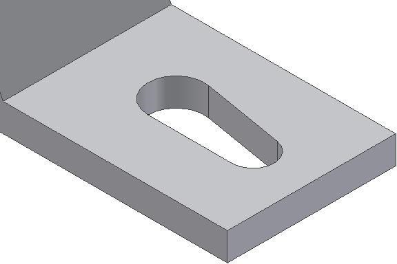
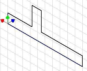
Step 5
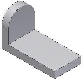
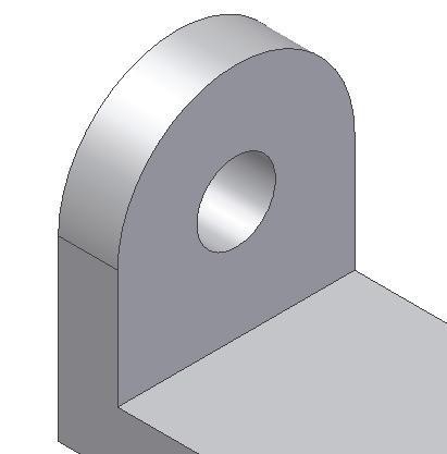
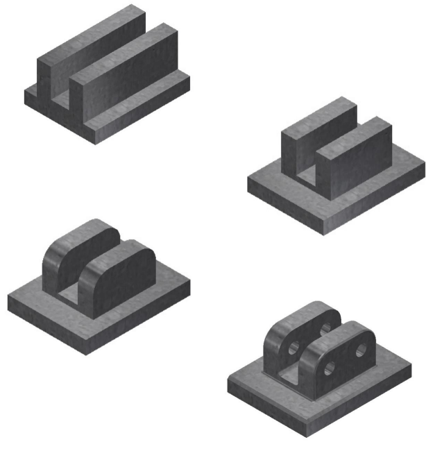
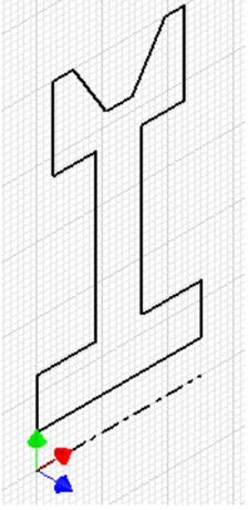
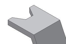
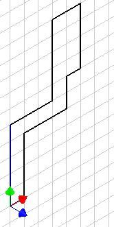
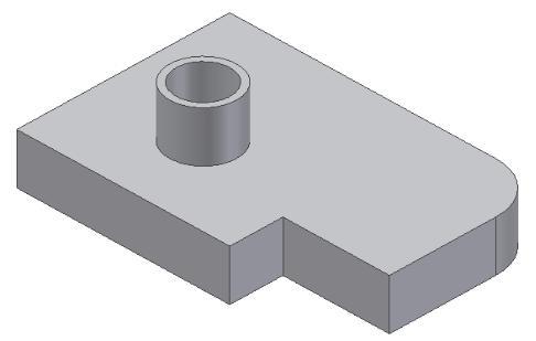
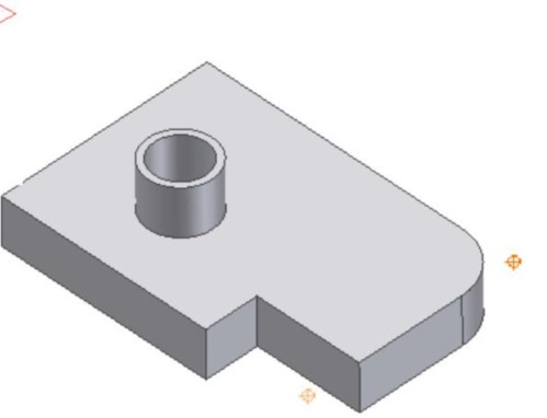
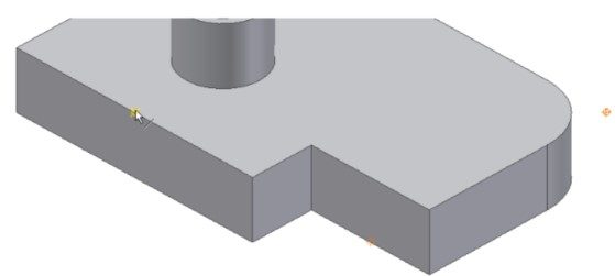
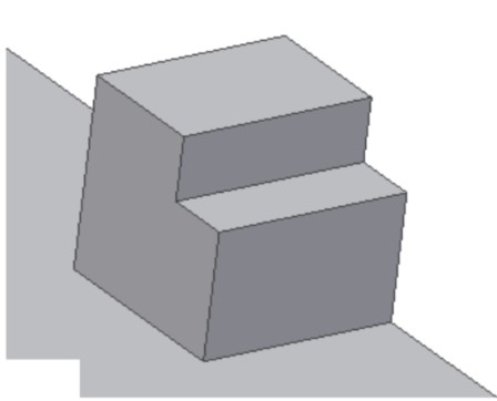
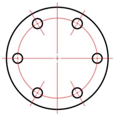
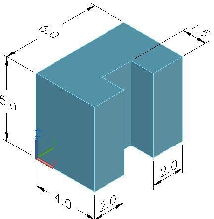
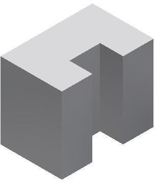
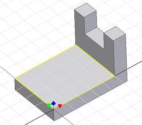
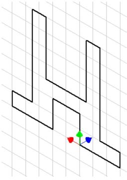
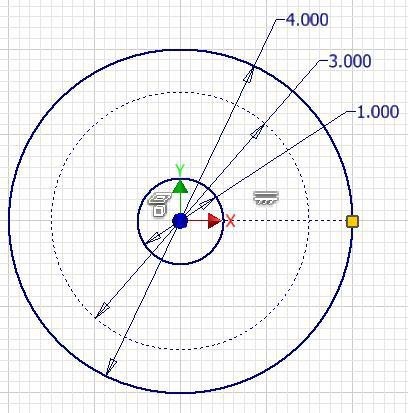
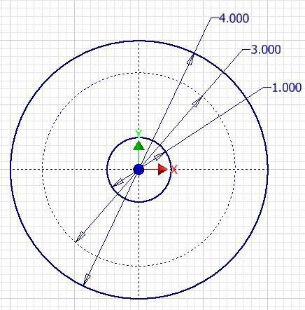
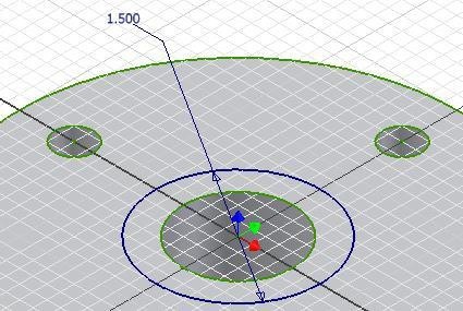
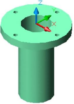
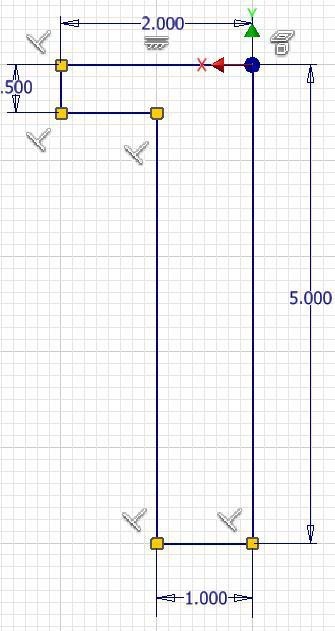
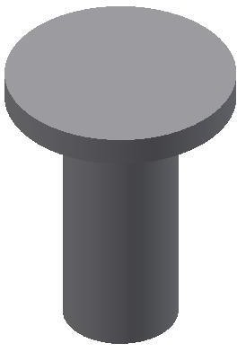
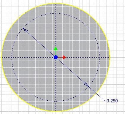
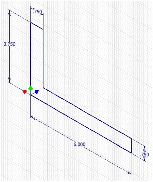
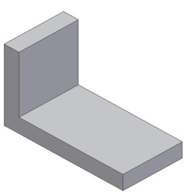
Draw the Base model of part 22-1B by extruding circles. Your Base model should appear as shown in the figure. (Figure Step 5)
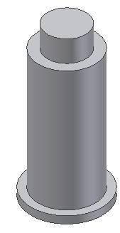
Figure Step 5
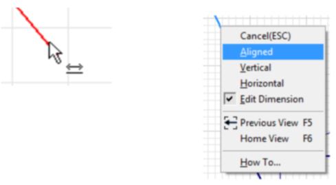
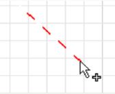
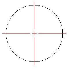
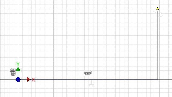
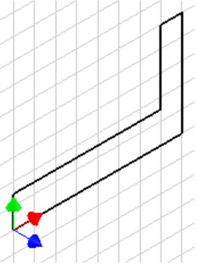
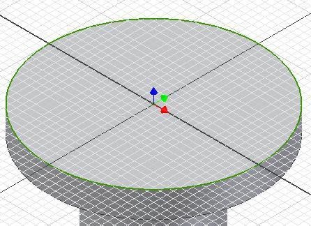
Step 6
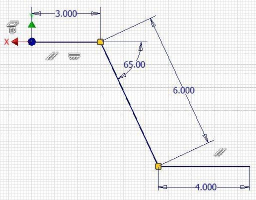
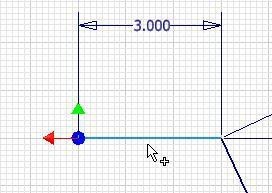
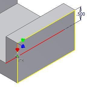
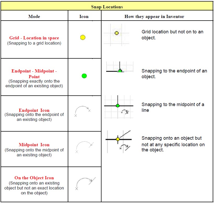
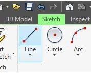
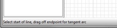
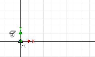
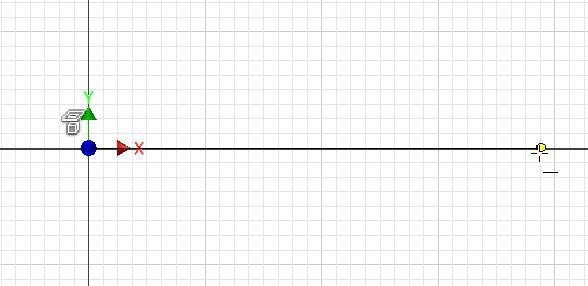
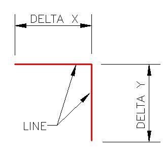
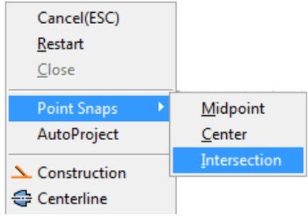
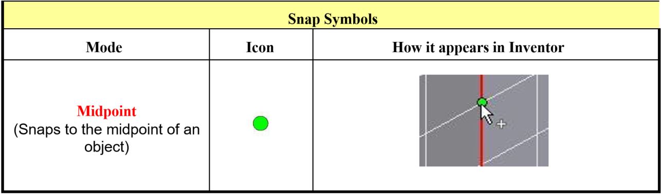
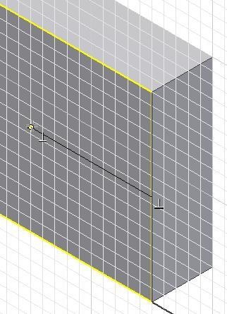
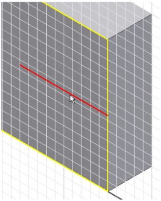
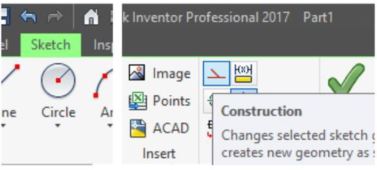
Start a new sketch on the top of the model and draw a construction line from the centre to the edge of the top plane along the Y axis as shown in the figure. Hint: Ensure that you draw the line along the Y axis by snapping to the centre of the circle and to the grid on the Y axis. The length of the line is not important. (Figure Step 6)
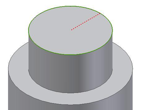
Figure Step 6
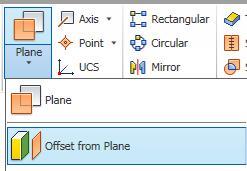
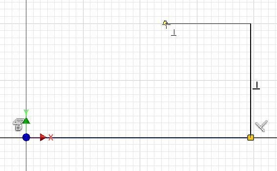
Step 7
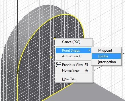
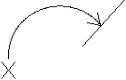
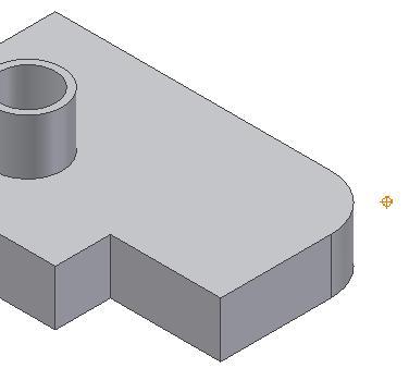
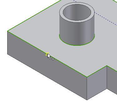
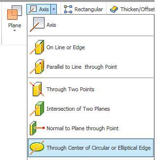
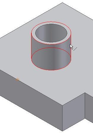
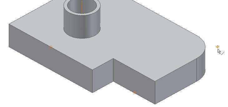
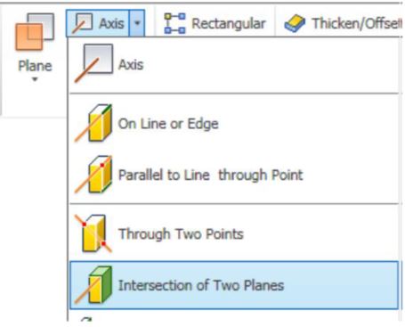
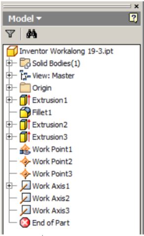
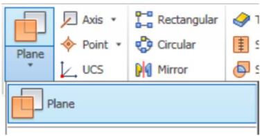
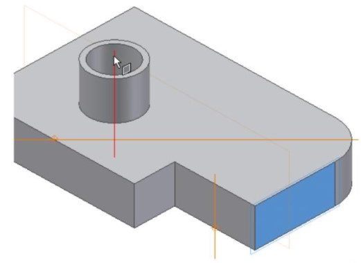
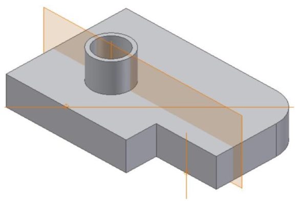
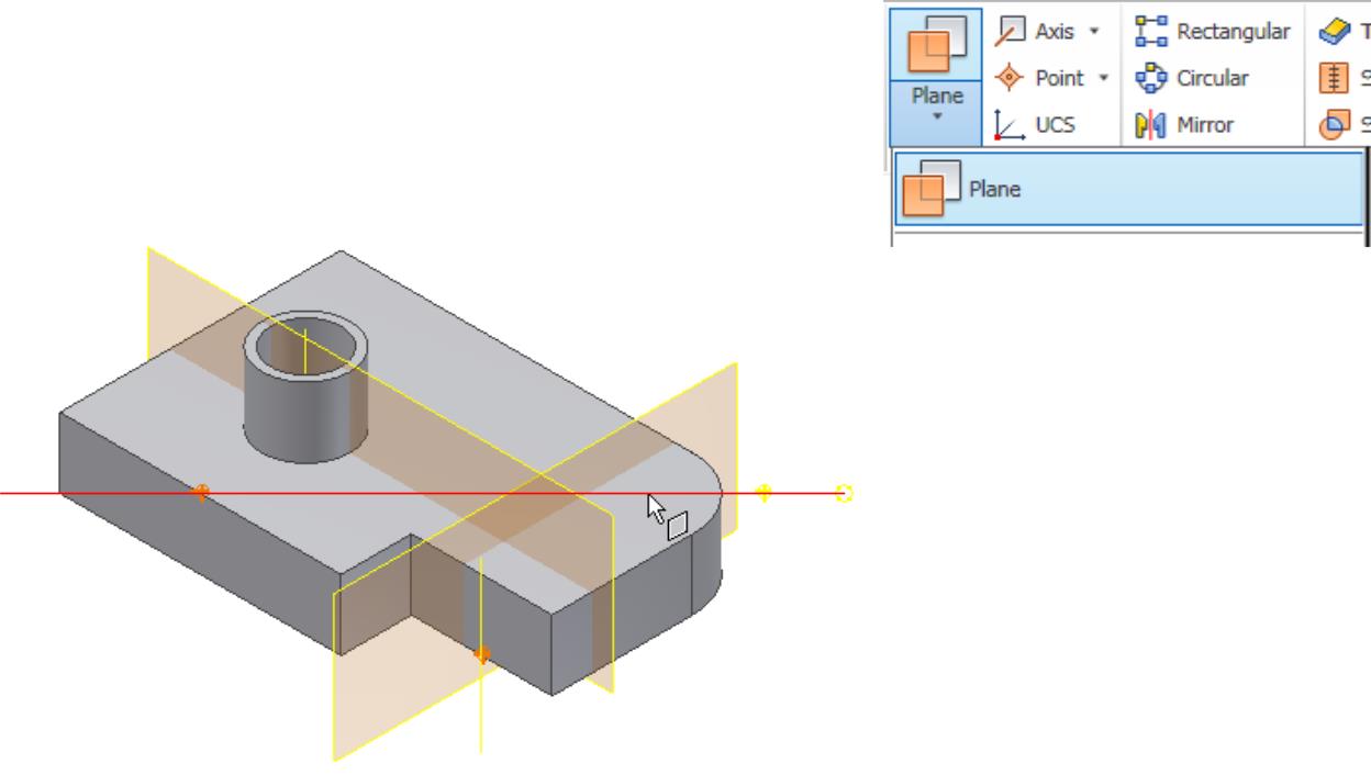
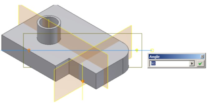
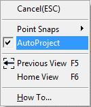
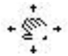
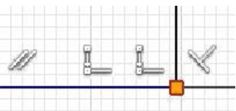
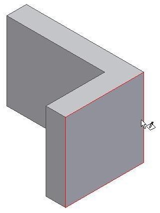
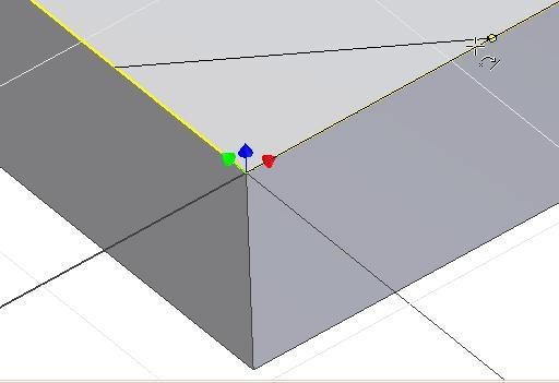
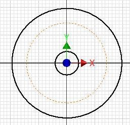
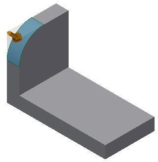
Insert a Work Plane in the centre of the model using the Perpendicular to a Line method. Enter the WORK PLANE command and move the cursor to the end of the construction line. The Work Plane icon will display as shown in the figure. Click the end of the line when the icon displays. (Figure Step 7)
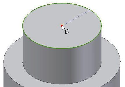
Figure Step 7
USER TIP: Before drawing each part, the orientation of the part when it is placed in the future assembly, should be considered. Doing that, will save a lot of time when creating the assembly model since it can be placed without any manipulation.
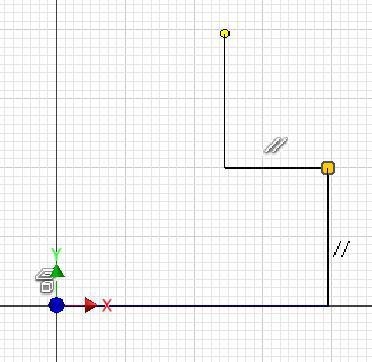
Step 8
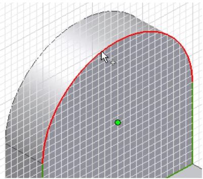
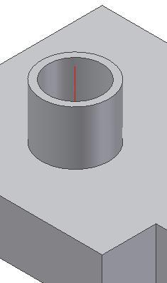
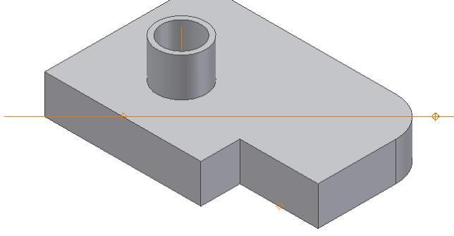
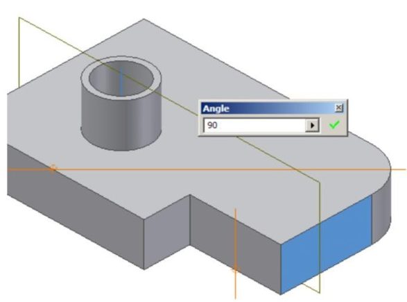
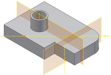
Move the cursor onto the Y axis and it will display as shown in the figure. When the Y axis is displayed, click it and the Work Plane will display as shown. (Figure Step 8A and 8B)
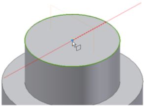
Figure Step 8A
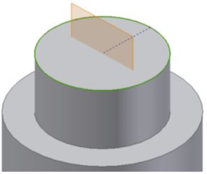
Figure Step 8B
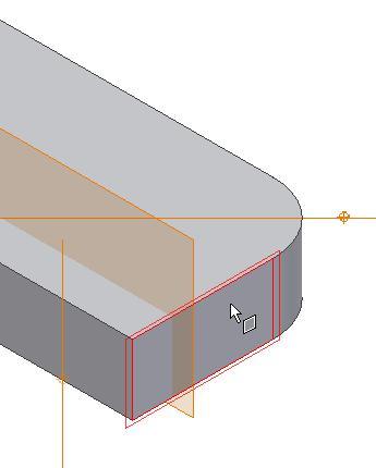
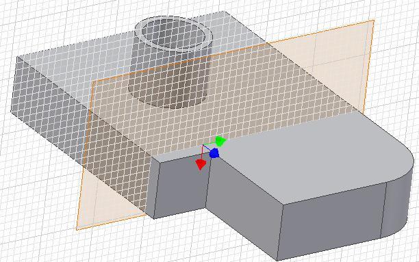
Step 9
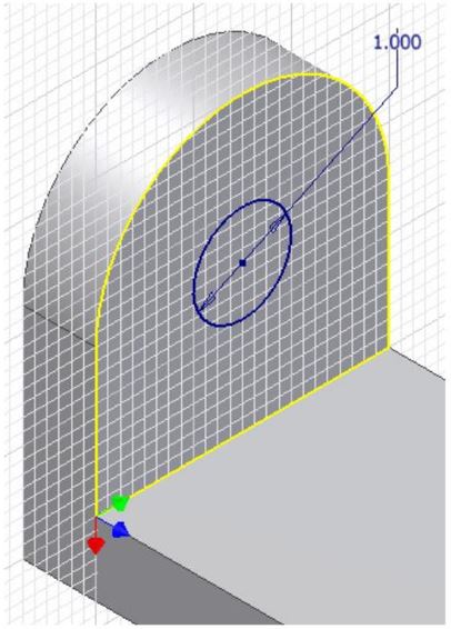
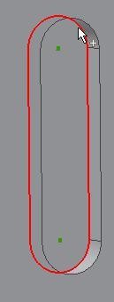
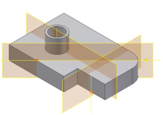
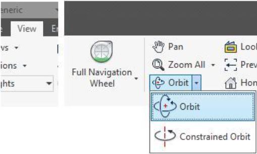
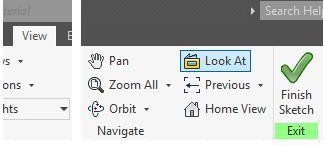
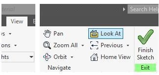
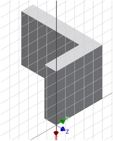
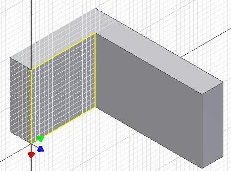
Enlarge the Work Plane to extend it past the edges of the model. One way to do this is to use the LOOK AT/VIEW FACE command and change the view so that it is looking perpendicular to the plane as shown in the figure. (Figure Step 9)
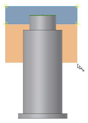
Figure Step 9
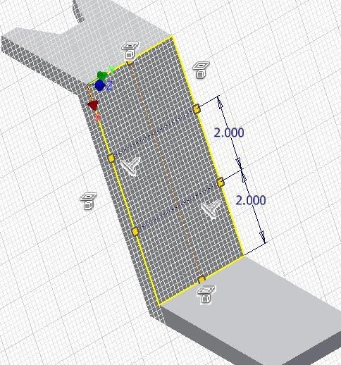
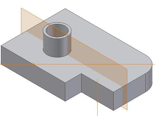
Step 10
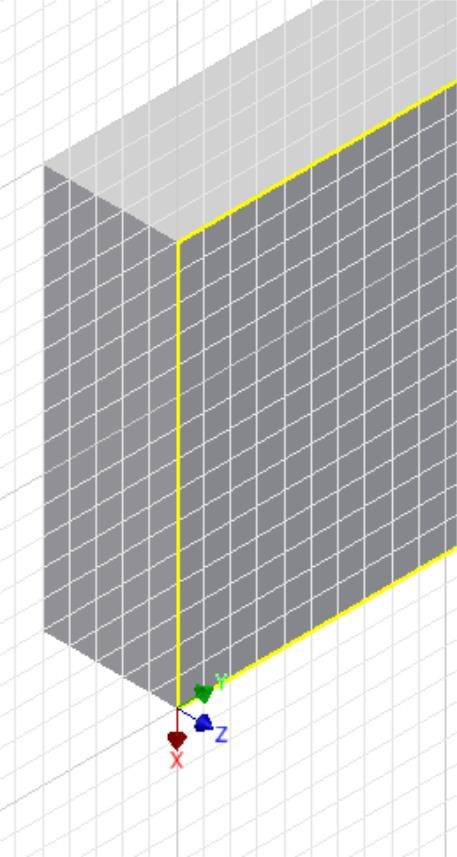
Start a new sketch on the Work Plane. (Figure 10)
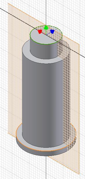
Figure Step 10
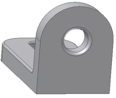
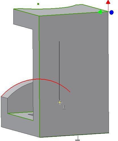
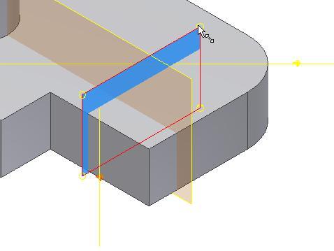
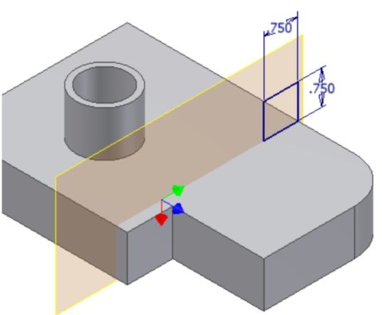
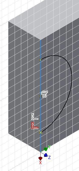
Step 11
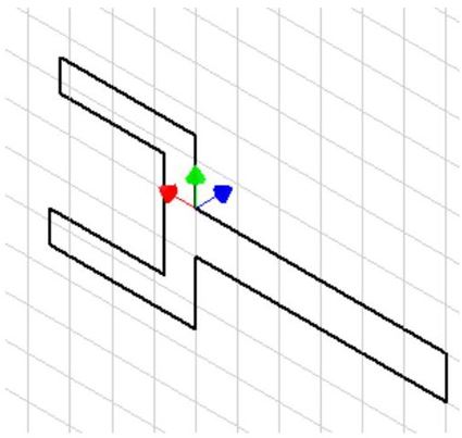
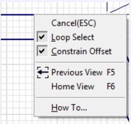
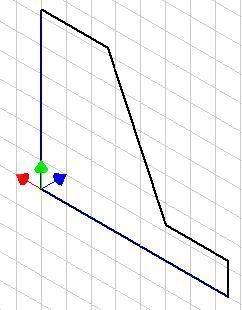
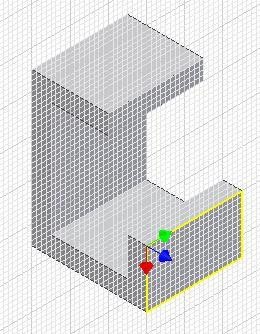
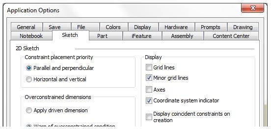
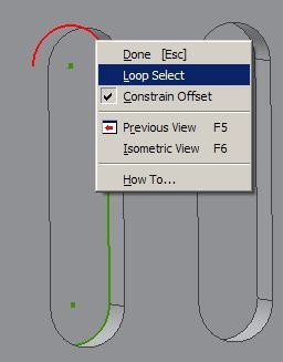
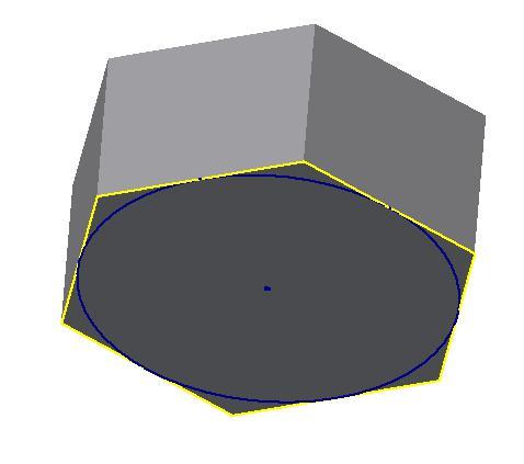
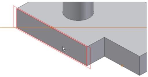
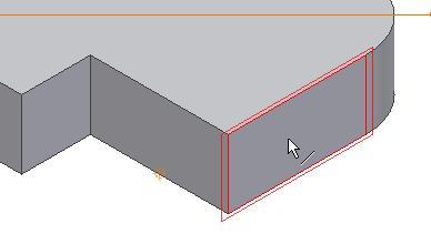
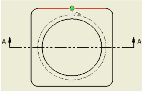
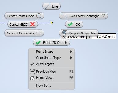
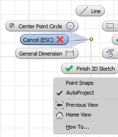
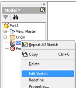
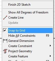
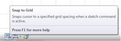
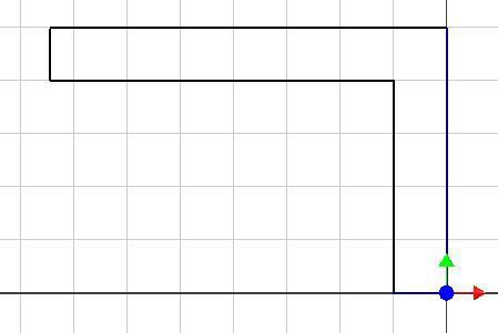
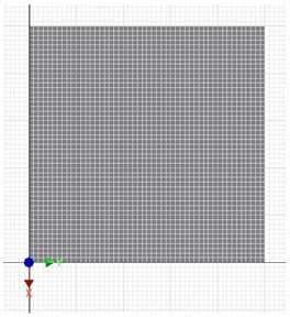
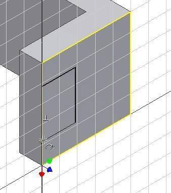
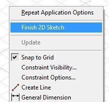
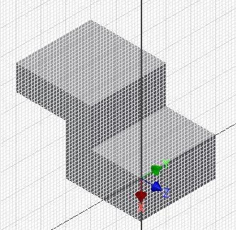
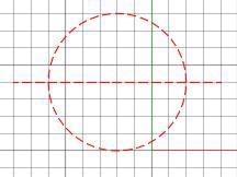
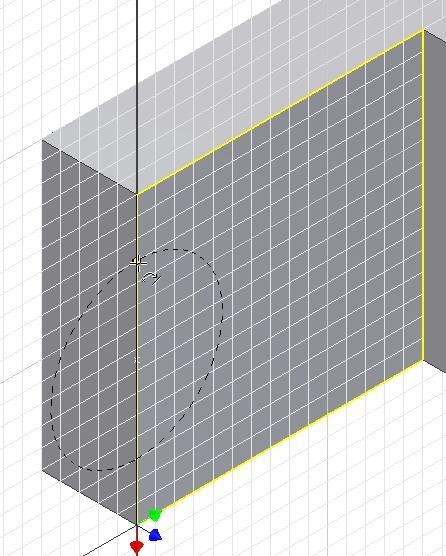
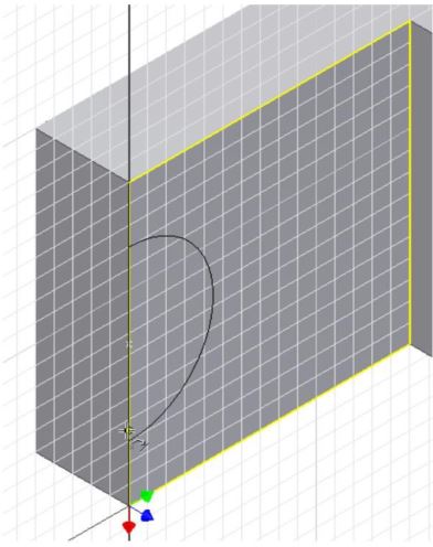
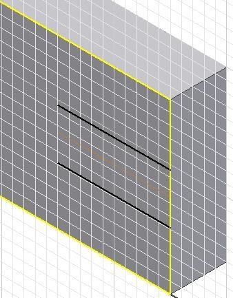
Enter the SLICE GRAPHIC command (F7) and the model will display from the sketching plane back. Disable the grid display. It is easier to draw this sketch without the grid. (Figure Step11)
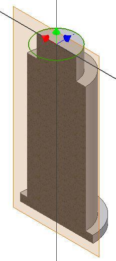
Figure Step 11
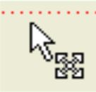
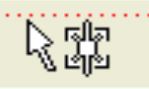
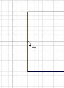
USER TIP: When enlarging the work plane, the cursor must display as the Stretch Move Stretch Cursor (two arrows) as shown. If you Cursor Cursor have trouble changing the cursor from the Move Cursor, zoom in closer and move the cursor onto one of the corners of the plane.
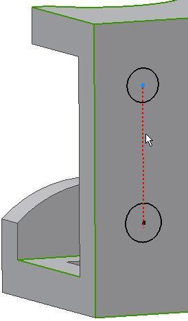
Step 12
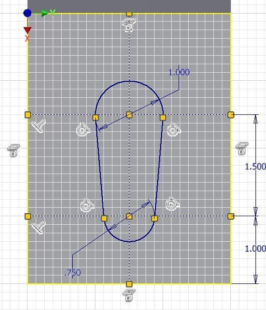
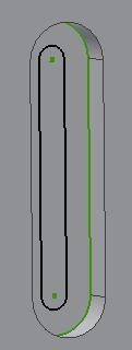
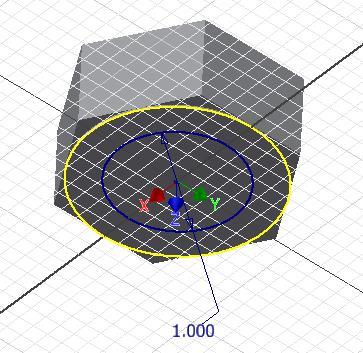
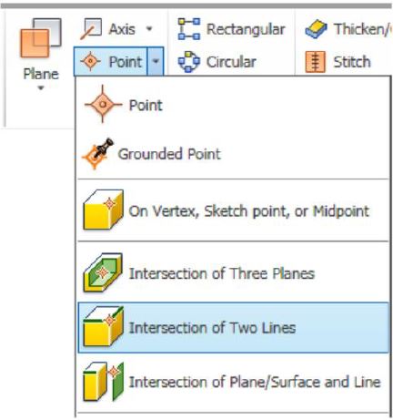
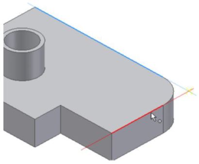
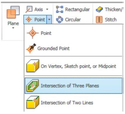
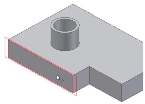
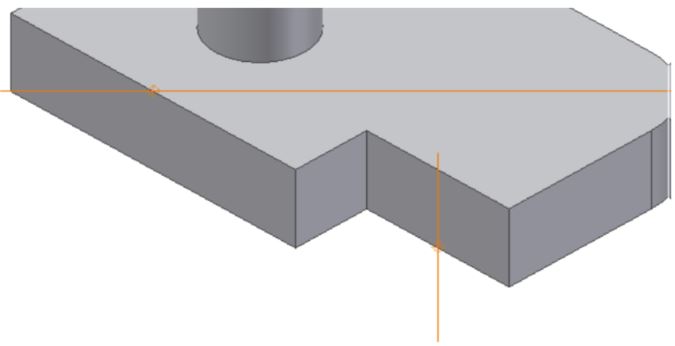
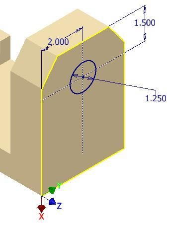
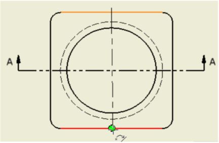
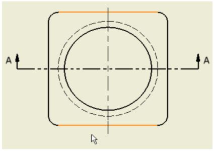
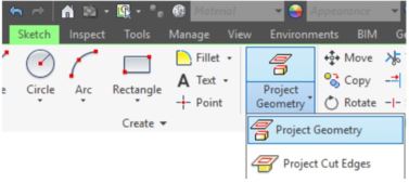
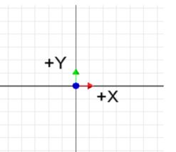
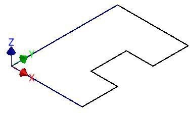
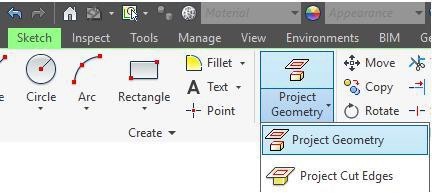
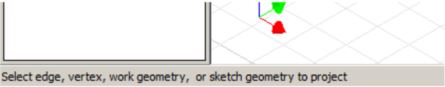
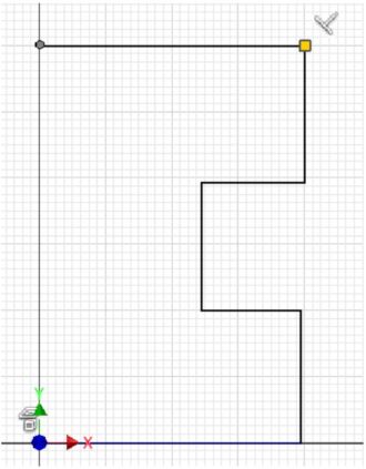
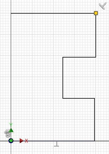
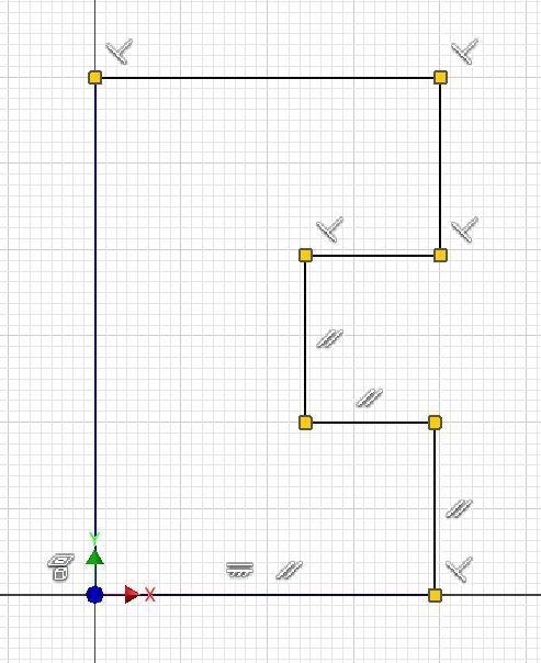
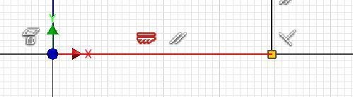
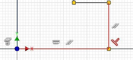
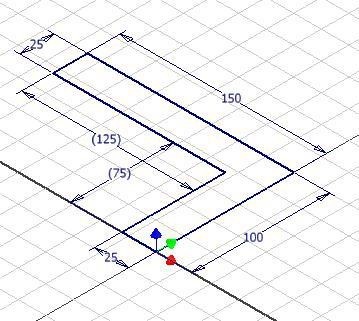
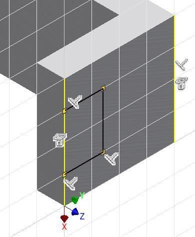
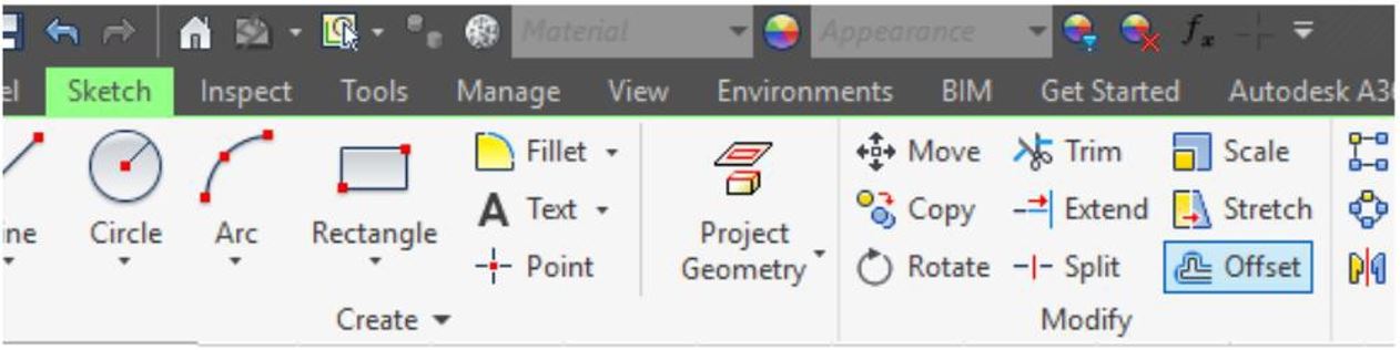
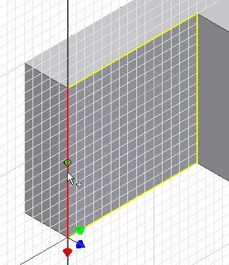
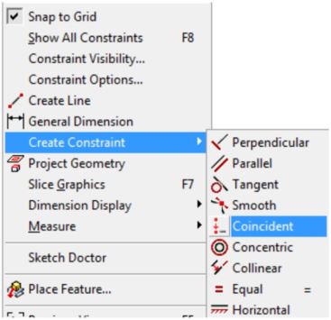
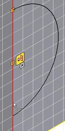
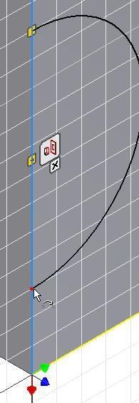
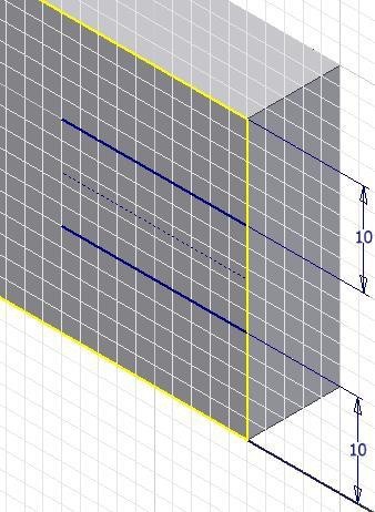
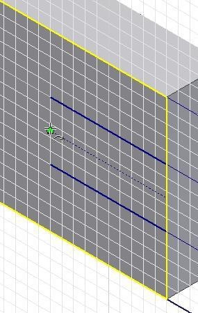
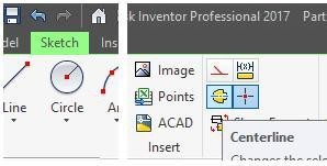
Using the PROJECT GEOMETRY command, project the Z axis and the X axis onto the sketching plane. (Figure Step 12A and 12B)
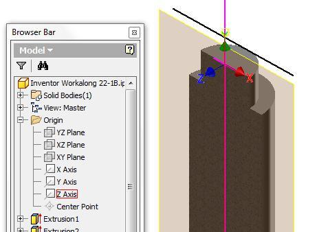
Figure Step 12A
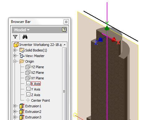
Figure Step 12B
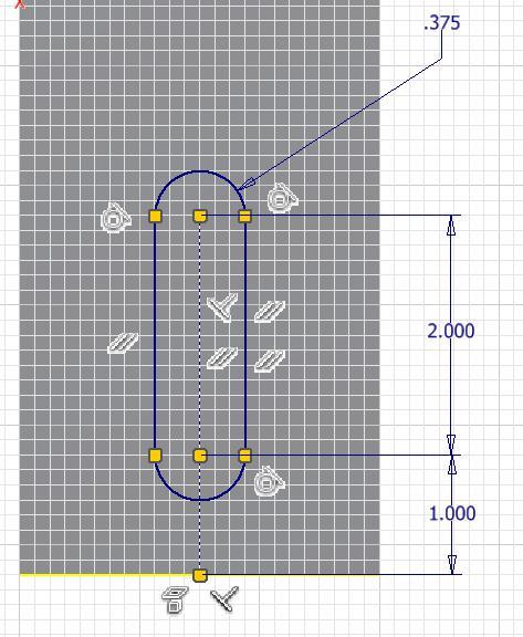
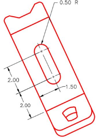
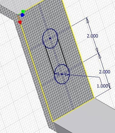
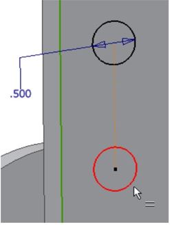
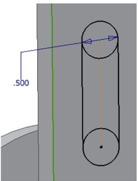
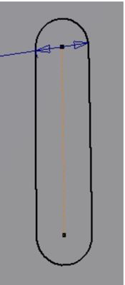
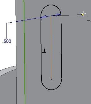
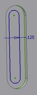
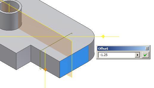
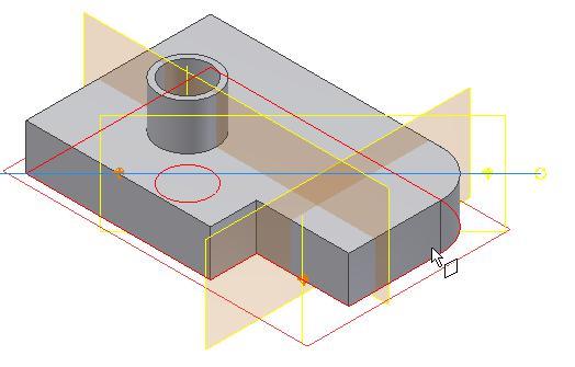
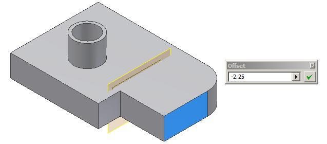
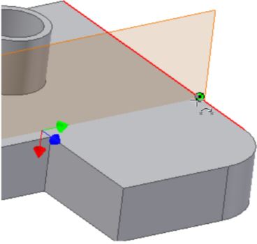
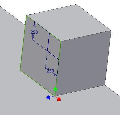
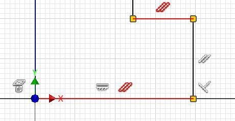
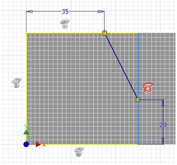
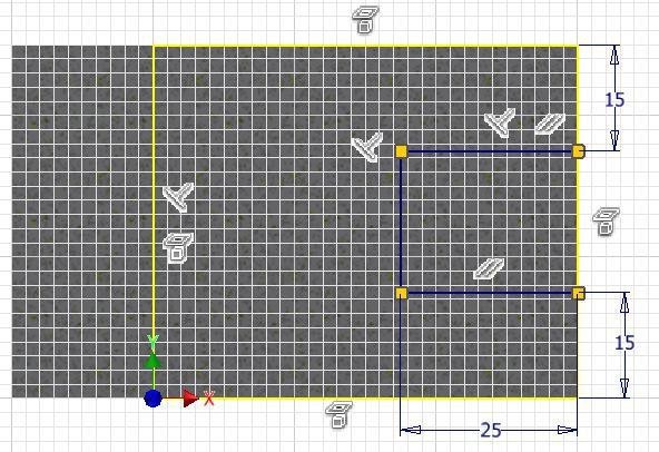
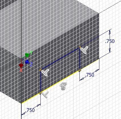
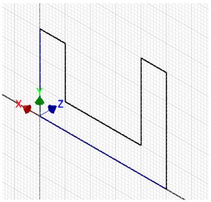
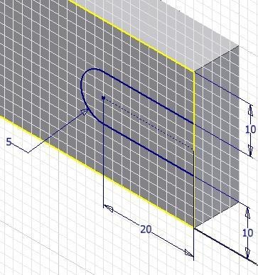
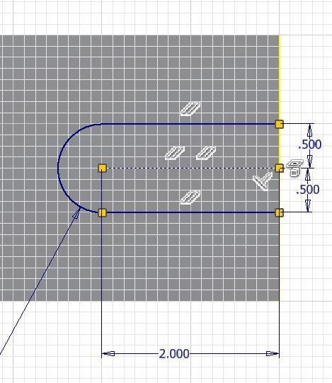
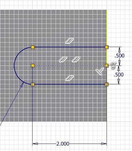
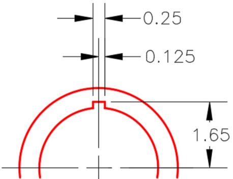
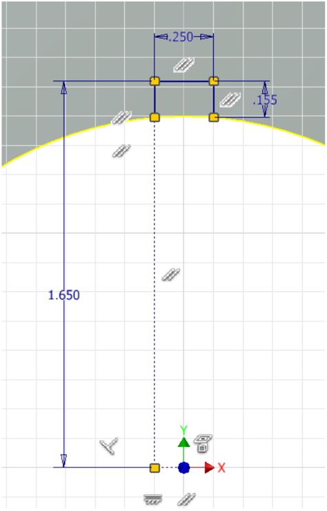
Step 13
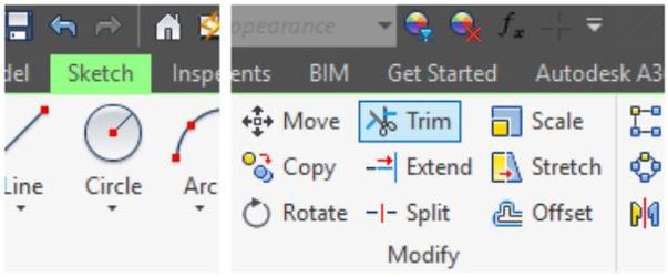
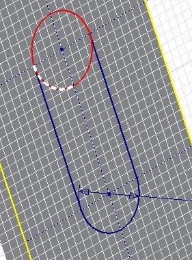
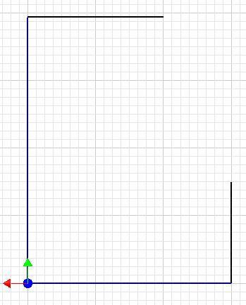
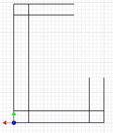
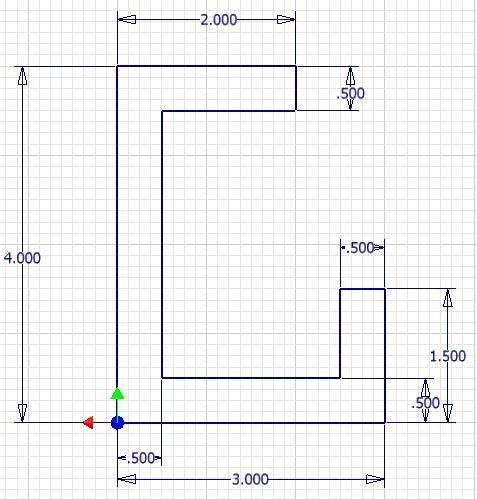
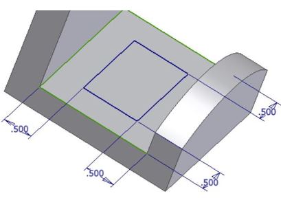
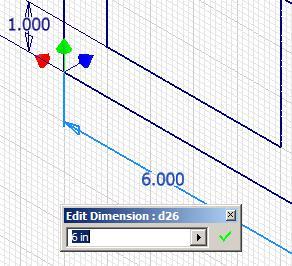
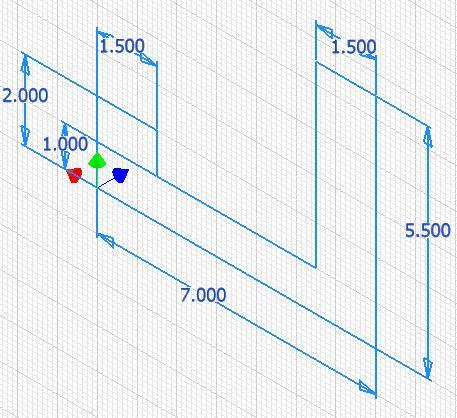
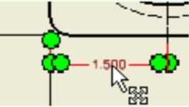
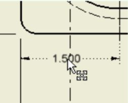
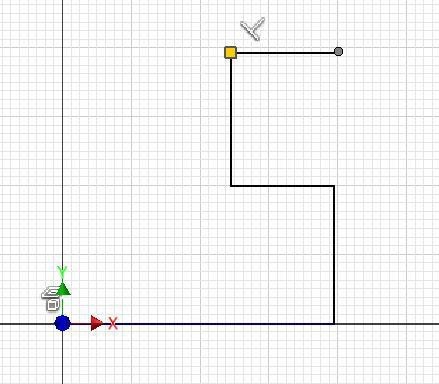
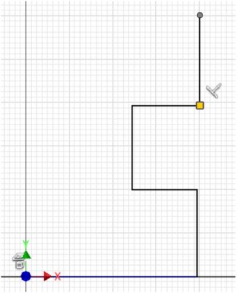
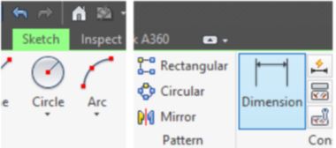
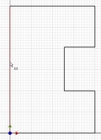
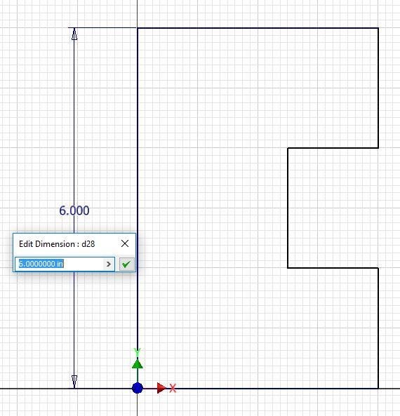
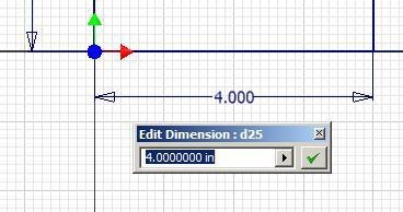
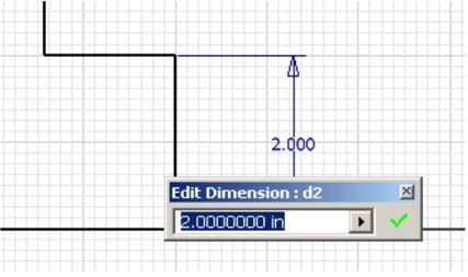
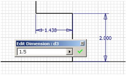
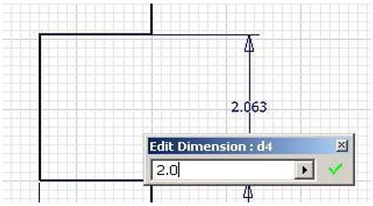
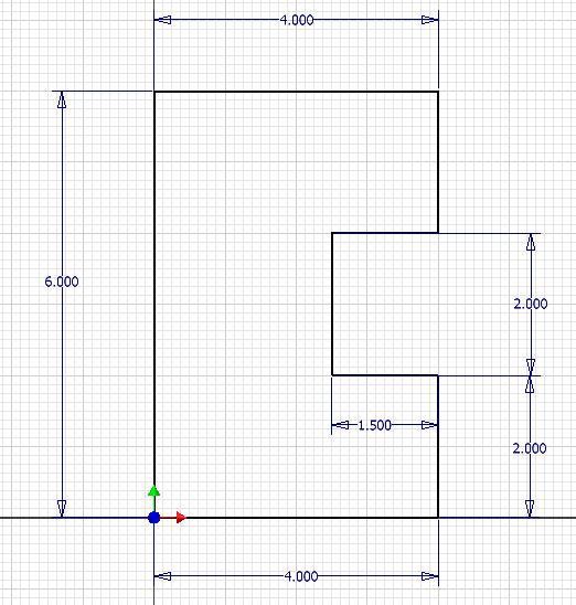
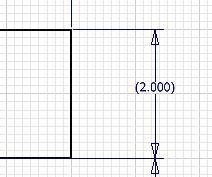
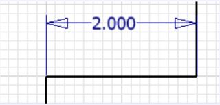
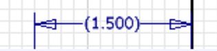
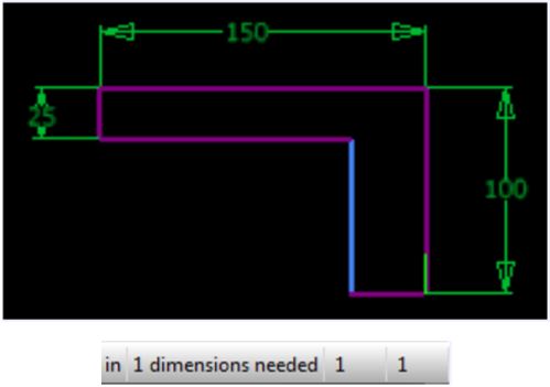
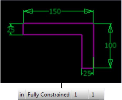
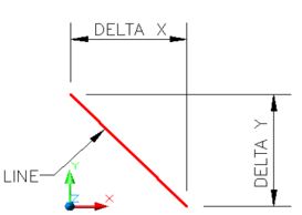
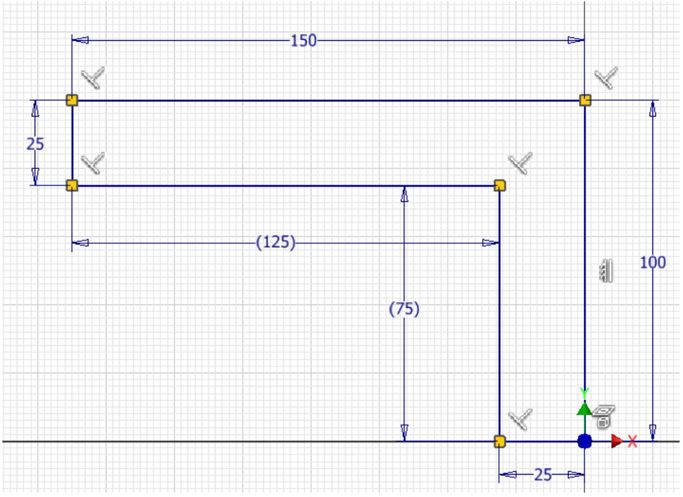
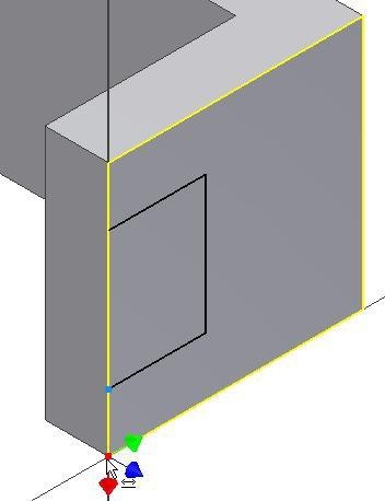
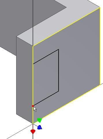
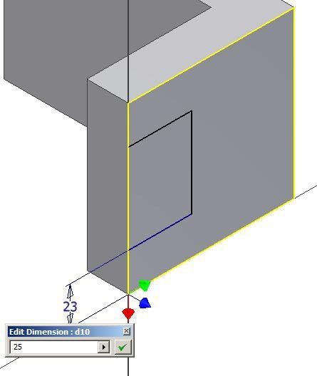
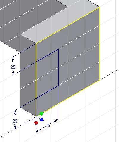
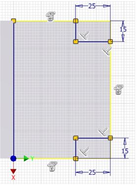
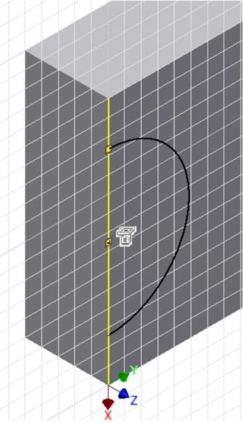
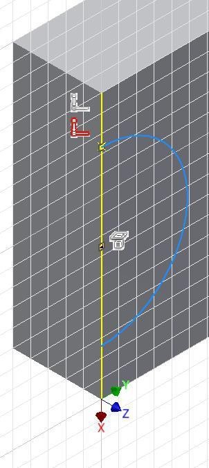
Using the OFFSET command, construct offsets to both the Z and X axis to start the construction of the slot. Trim the lines in the sketch and insert the dimensions to fully constrain the sketch. Ensure that you dimension from both sides of the Z axis as shown in the figure. (Figure Step 13A and 13B)
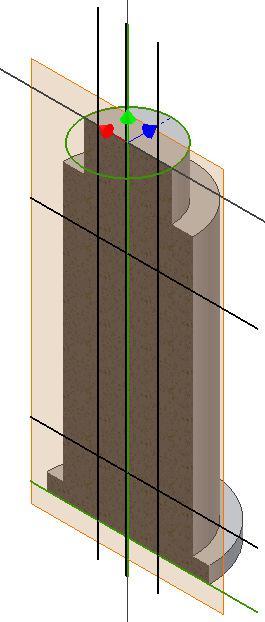
Figure Step 13A
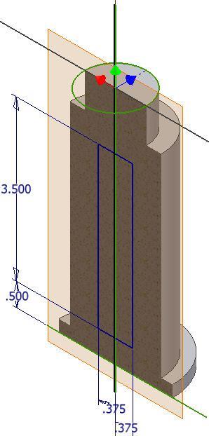
Figure Step 13B
MUST KNOW: An assembly file does do not contain any of the part files that are placed in the assembled model. It simply contains a reference to the part files. A reference is a link back to the part files. The part files that have been placed in an assembly file must be available to Inventor to display them when the assembly file is opened.
The project file keeps track of those links and will automatically keep track of the location of all the files. If an assembly file (.iam) is sent to a client or an associate, the part files (.ipt) that were placed in the assembly file must also be included otherwise they will not display when the file is opened.
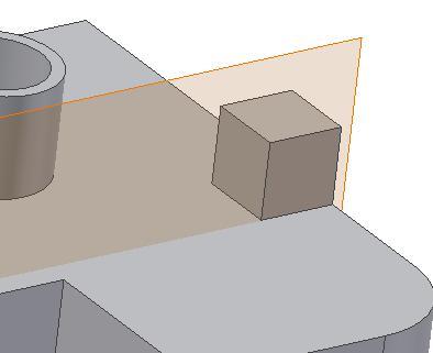
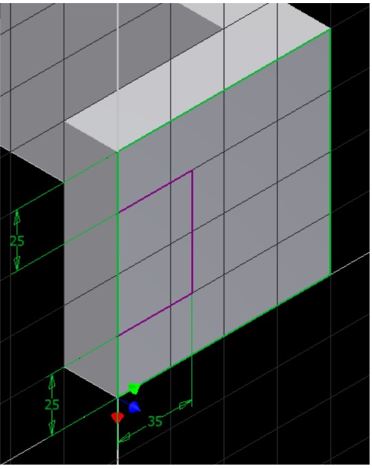
Step 14
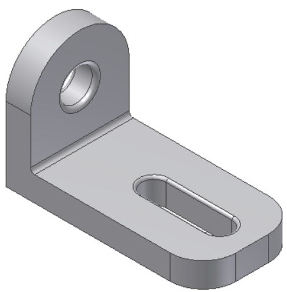
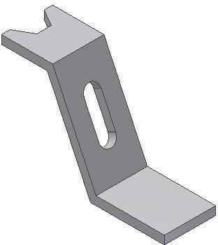
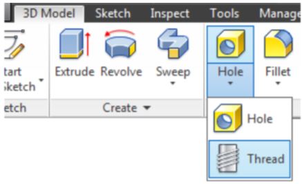
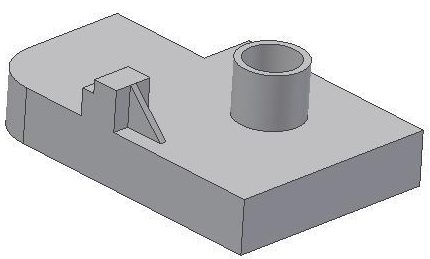
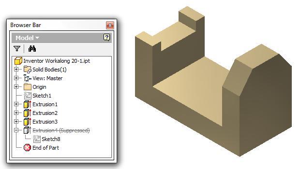
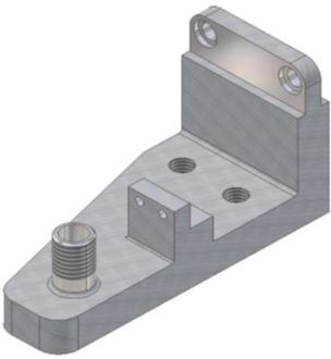
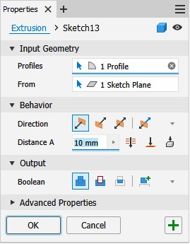
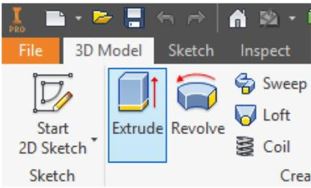
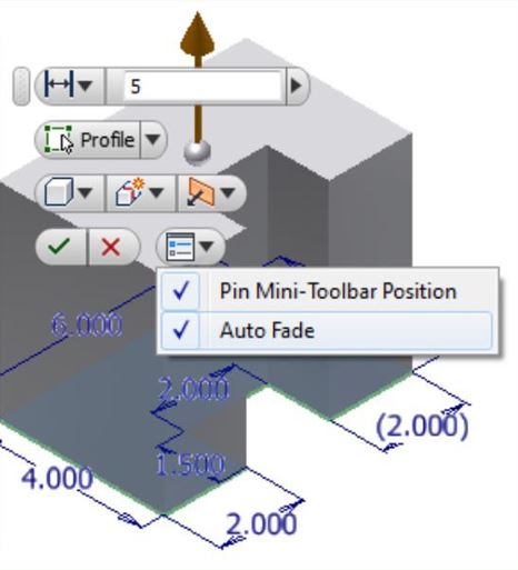
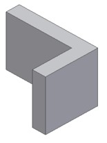
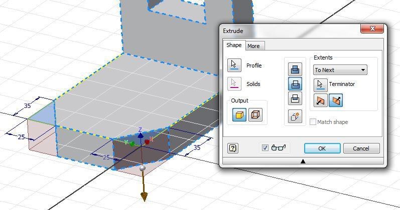
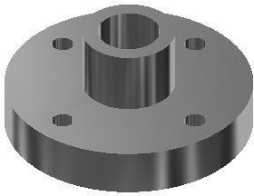
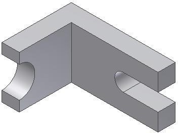
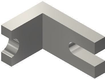
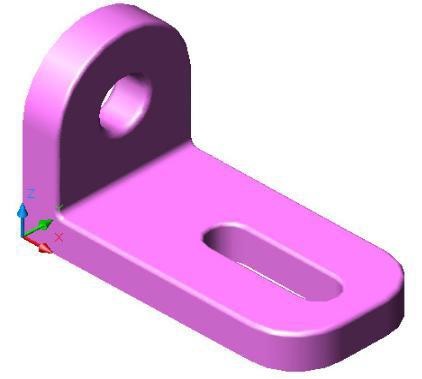
Extrude the sketch. Set it to extrude in both directions and to cut. Set the distance to All. Complete the part by adding the hole, the threads, the fillets, the colour, and the material as specified in Figure 14A, 14B, and 14C.
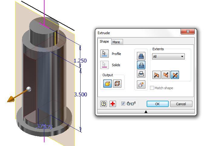
Figure Step 14A [Click to see image full size]
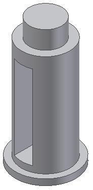
Figure 14B
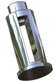
Figure 14C
Step 15
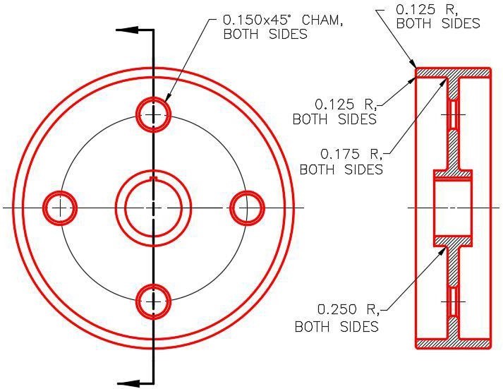
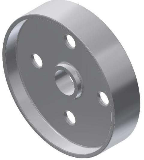
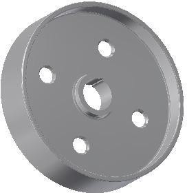
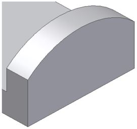
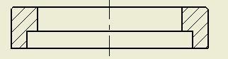
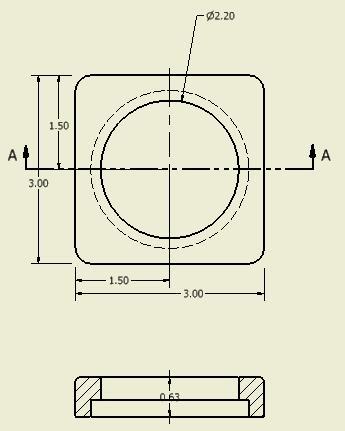
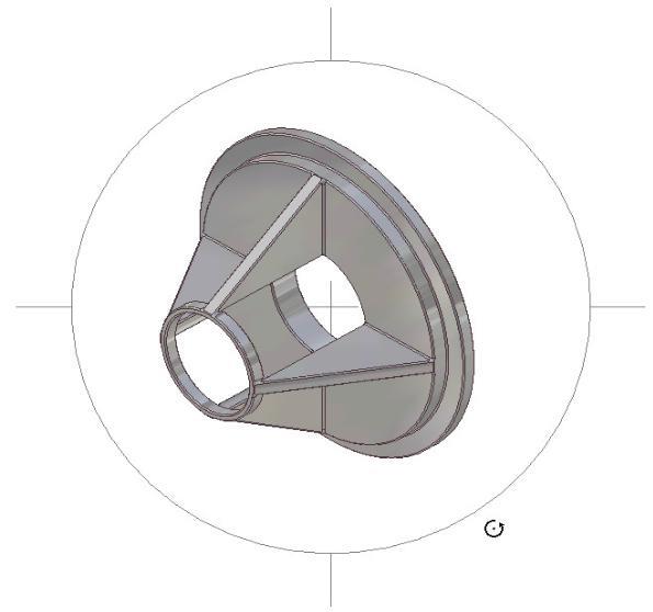
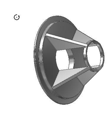
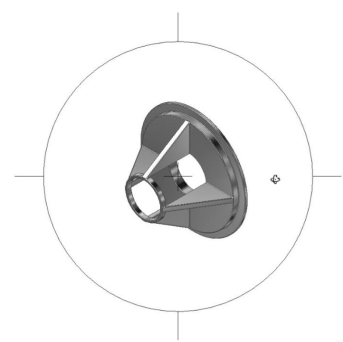
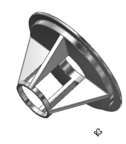
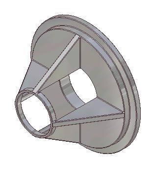
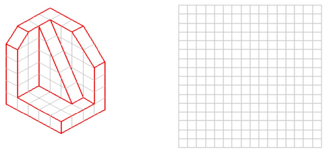
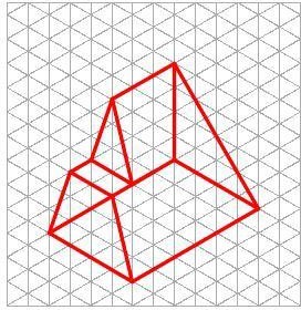
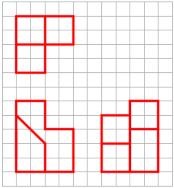
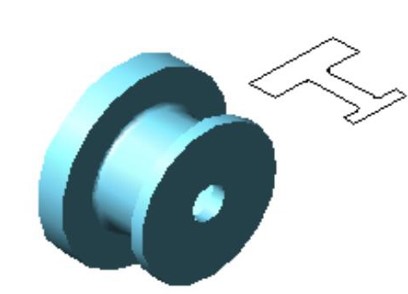
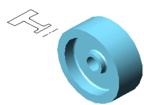
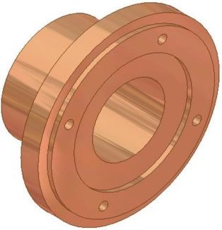
Create Part C. (Figure Step 15A, 15B, 15C, and 15D):
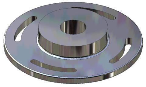
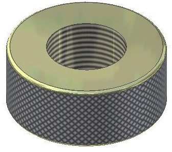
Part: Wedge Ring
Part Name: Inventor Workalong 22-1C
Template: English-Modules Part (in).ipt
Color: Titanium – Polished
Material: Titanium
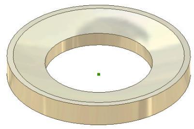
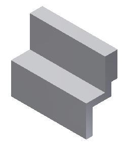
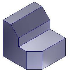
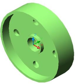
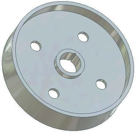
Figure Step 15A
Solid Model – Home View
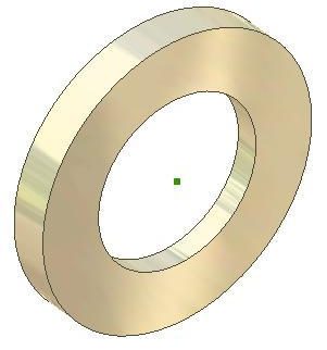
Figure Step 15B
Solid Model
– Orbited View
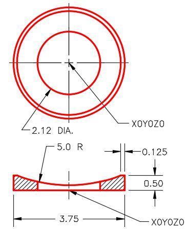
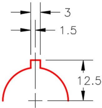
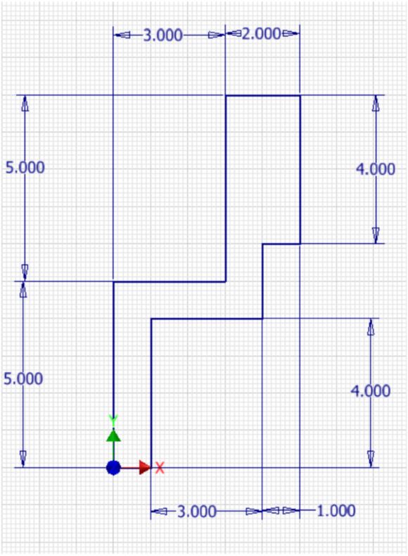
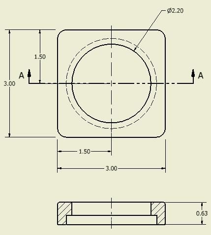
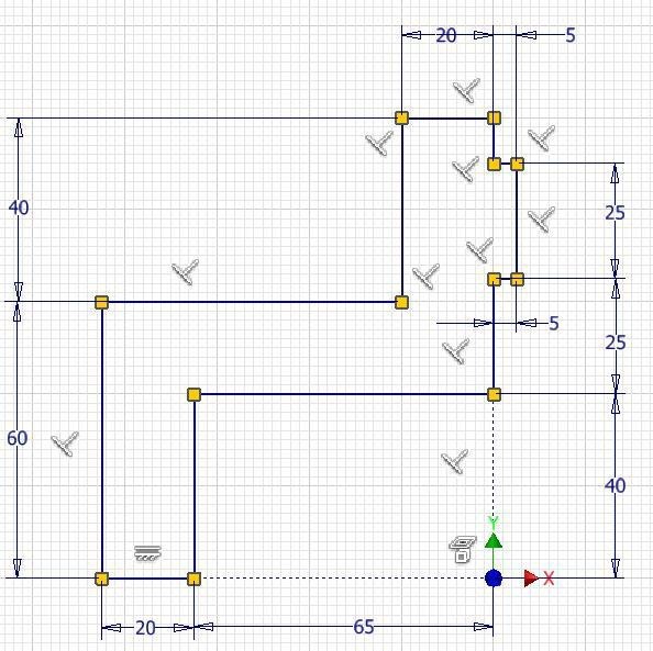
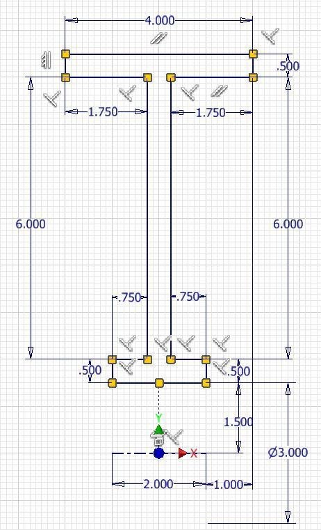
Figure Step 15C
Dimensioned Multiview Drawing
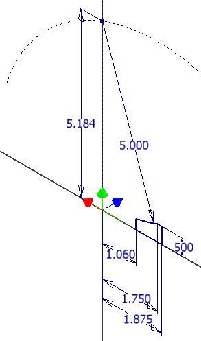
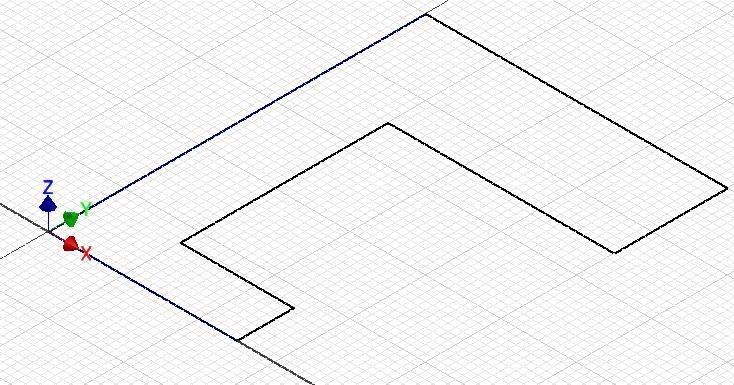
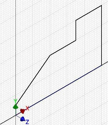
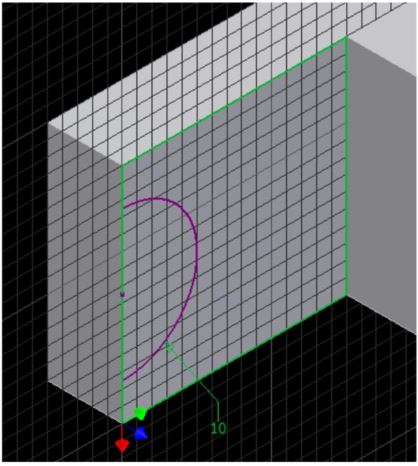
Figure Step 15D
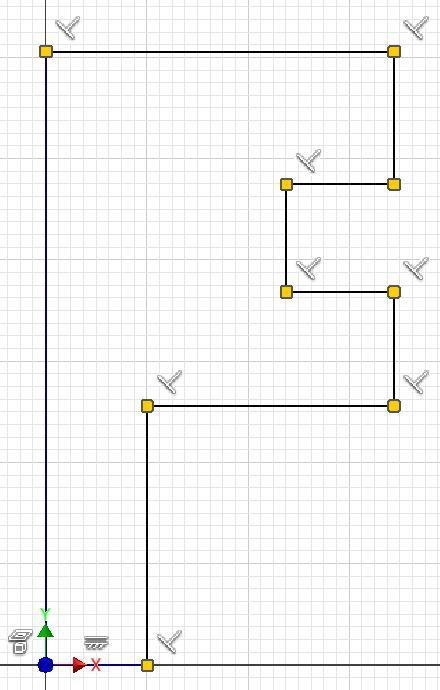
The Base Sketch
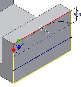
AUTHOR’S COMMENTS: If you project the X and Z axis onto the plane, the same way you did in Step 12 and then construct arcs and offset lines it will be much easier to construct the Base sketch for this part. The last step is to revolve the sketch to complete the solid model.
Step 16
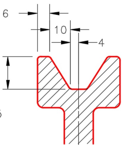
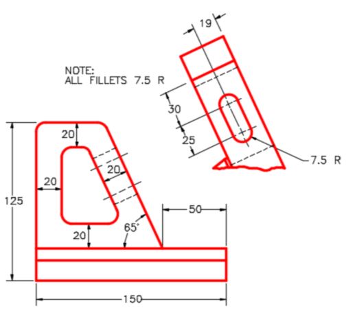
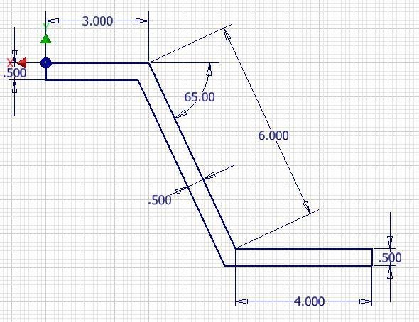
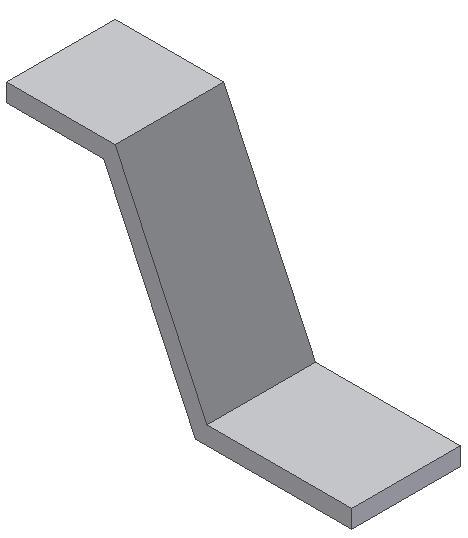
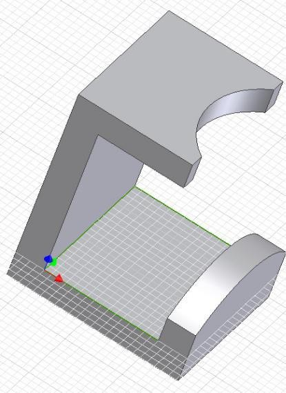
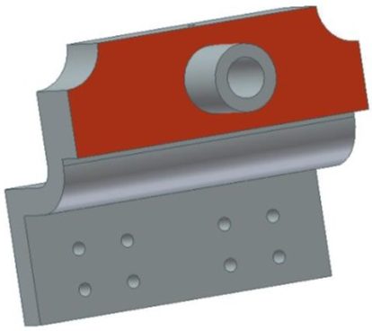
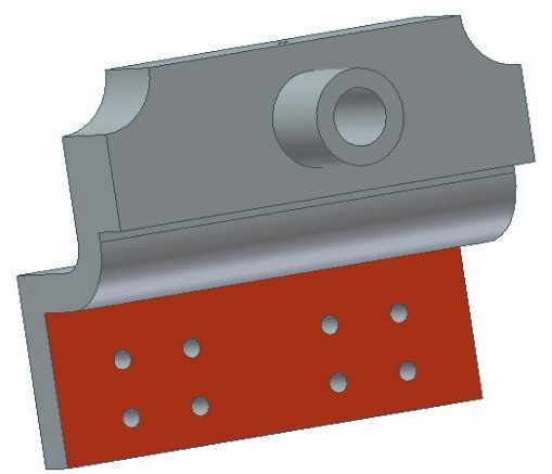
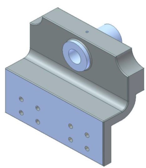
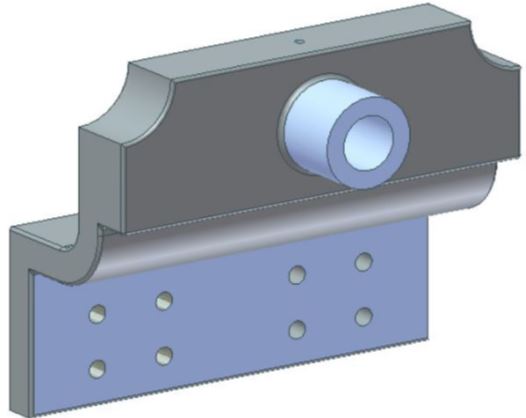
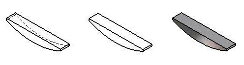
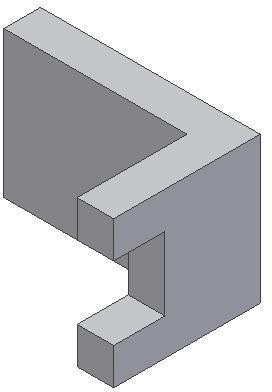
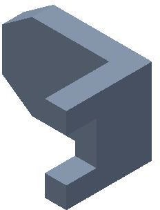
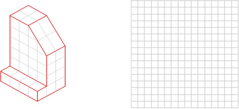
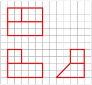
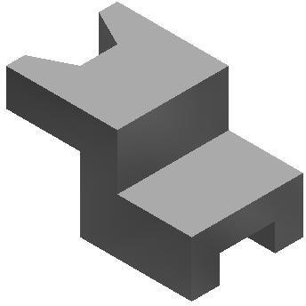
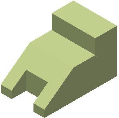
Construct Part D. (Figure Step 16A and 16B)
Part: Wedge
Part Name: Inventor Workalong 22-1D
Template: English-Modules Part (in).ipt
Color: Chrome – Polished
Material: Steel
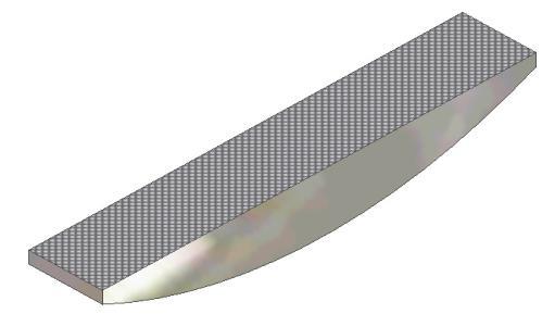
Figure Step 16A
Solid Model – Home View
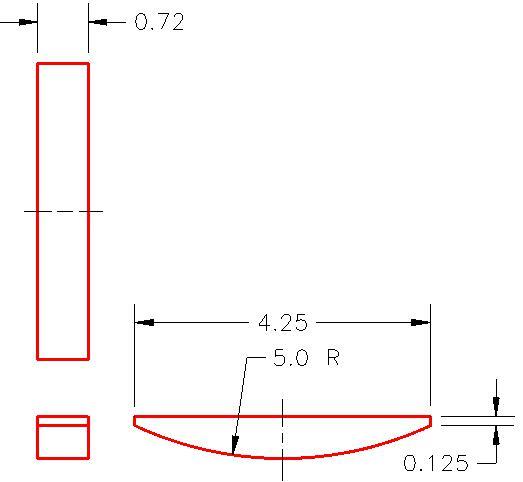
Figure Step 16B
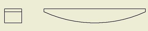
Dimensioned Multiview Drawing [Click to see image full size]
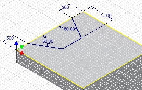
Step 17
Change the face colour of the top face of the part to: Metal Steel (Knurled) as shown in Figure 16A.
Step 18
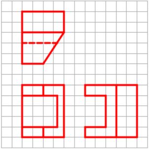
Construct Part F as follows: (Figure Step 18A and 18B)
Part: Handle
Part Name: Inventor Workalong 22-1E
Template: English-Modules Part (in).ipt
Color: Metal-AL-6061 – Machined
Material: Steel
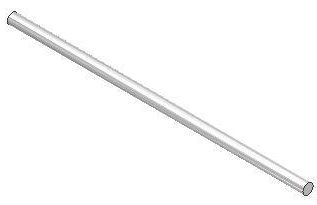
Figure Step 18A
Solid Model – Home View
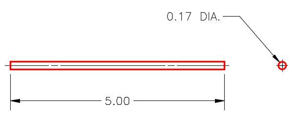
Figure Step 18B
Dimensioned Multiview Drawing
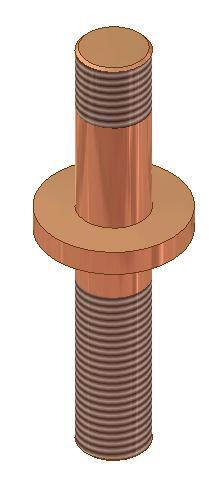
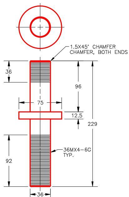
Step 19
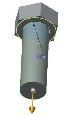
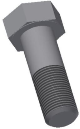
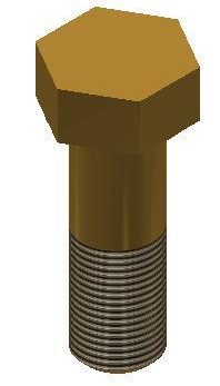
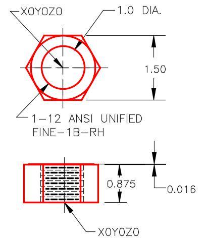
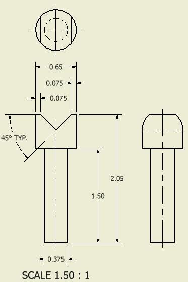
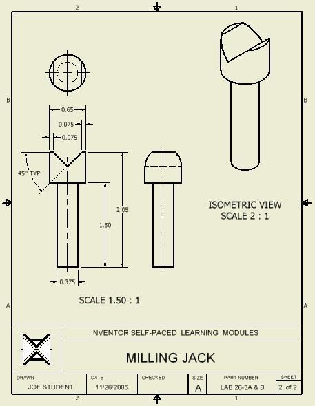
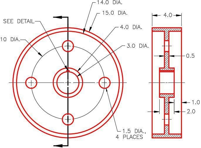
Construct Part E as follows: (Figure Step 19A, 19B, and 19C)
Part: Screw
Part Name: Inventor Workalong 22-1F
Template: English-Modules Part (in).ipt
Color: Metal-AL-6061 – Machined
Material: Steel
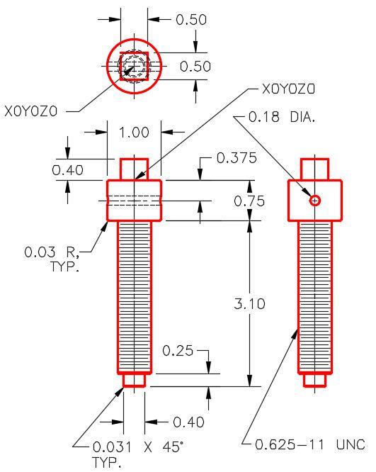
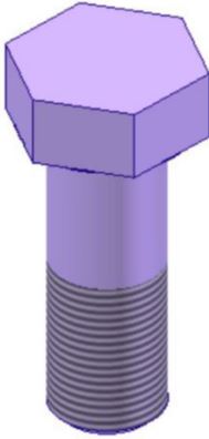
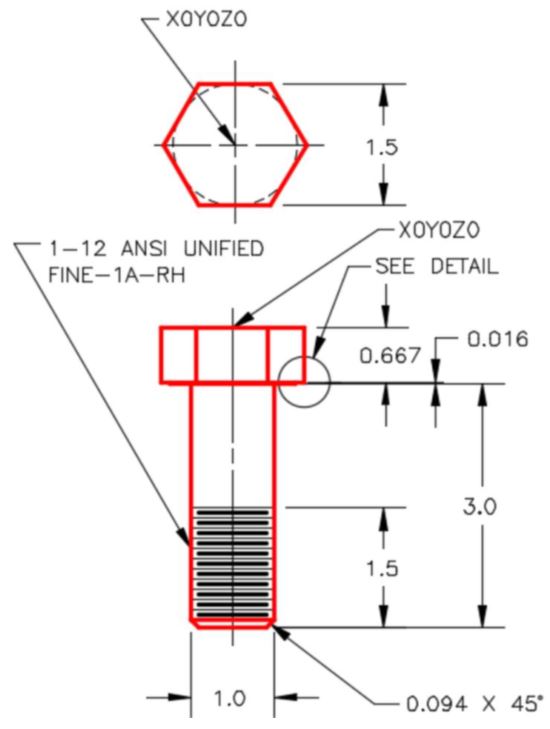
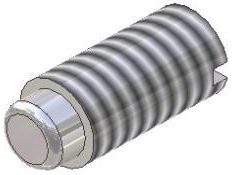
Figure Step 19A
Dimensioned Multiview Drawing [Click to see image full size]
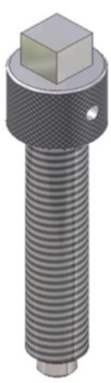
Figure Step 19B
Solid Model –
Home View
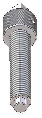
Figure Step
19C
Solid Model –
Orbited View
Step 20
Change the face colour of the cylindrical top of the part to: Metal Steel (Knurled) as shown in the solid model figure.
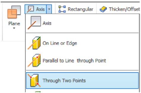
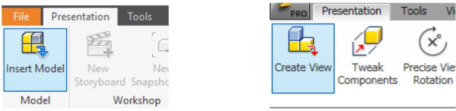
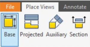
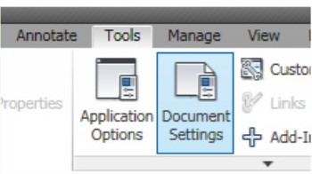
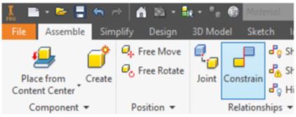
The PLACE COMPONENT command is used to insert a part or a component into an assembly file.
Shortcut: P
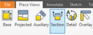
The PLACE CONSTRAINT command is used to apply constraints of one part to another in the assembled model.
Shortcut: C
Grounded Parts
By default, the first part that is placed into an assembly file will be grounded. A grounded part is a part that has all of it degrees of freedom removed and is fully constrained in that file. It is important to ground at least one part of every assembly. If no parts are grounded, the assembly can be moved around in model space. Once one part is grounded, the other parts can be constrained to it making their movement relative to the grounded part. If required, more then one part can be grounded.
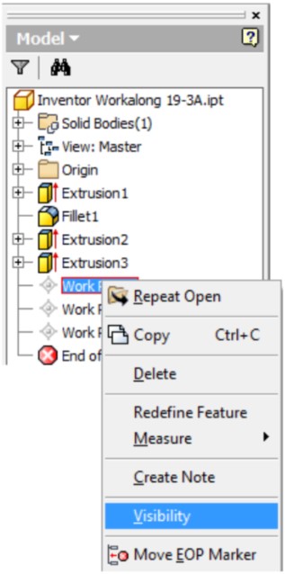
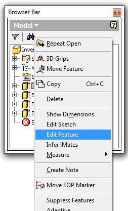
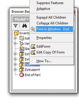
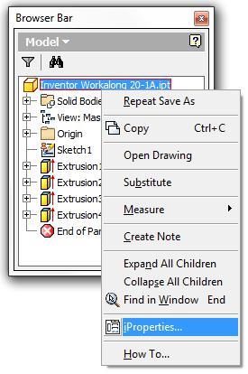
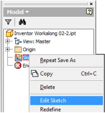
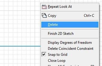
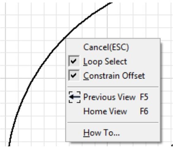
In the Browser bar, a grounded part will display a Push Pin icon as shown in Figure 22-3 and 22-4. To enable or disable a part being grounded, right-click the part in the Browser bar. In the Right-click menu, select Grounded. In Figure 22-5, the selected part is currently grounded, enabled and visible.
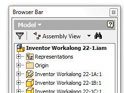
Figure 22-3 Grounded Part as it Displays in the Browser Bar
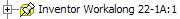
Figure 22-4
Grounded Part Icon
Part Visibility
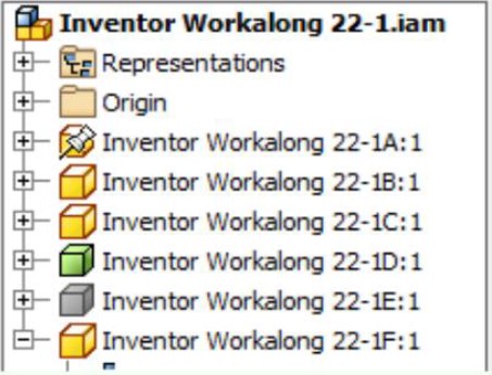
The visibility of parts in an assembly can be enabled or disabled. When the part’s visibility is disabled in the assembly, the part’s icon in the Browser bar will display greyed out.
Enabled Parts
Parts can be enabled or disabled in the assembly file. If a part is enabled, it displays and can be selected in the assembly. If it is disabled, only an outline displays and It cannot be selected. Sometimes it is easier to disable some parts to make it easier to place additional parts.
Assembly Constrains
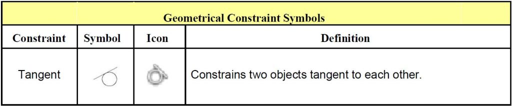
There are many different constraints used when creating an assembly. In this module, only the mate constraint will be taught. A mate constraint constrains two assembled parts to one another by mating their centerlines and/or by mating a face on one part to a face on the other part. Mating is the most common way to assemble two parts together. It often takes more then one constraint to assemble two parts together. Both parts must have a symmetrical feature to mate them using the centerline method.
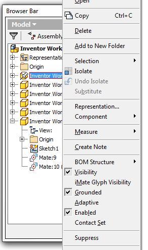
Figure 22-5
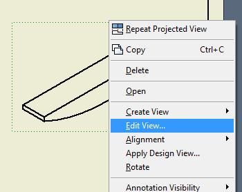
The Right-click Menu for a Part
in an Assembly File
MUST KNOW: By default, the first part that is placed into an assembly file will be grounded. A grounded part is a part that has all of it degrees of freedom removed and is fully constrained in that file. It is important to ground at least one part in every assembly since if no parts are grounded, the assembly can be moved around model space. Once one part is grounded, the other parts can be constrained to it making their movement relative to the grounded part.
USER TIP: The Browser bar contains a great deal of information about the active assembly file. The grounded part has a Push Pin icon. If a part is disabled, it will display a green part icon and if its visibility is disabled, the part icon will be grey as you can see in the figure.
WORKALONG: Creating an Assembly
Step 1
Check the default project and if necessary, set it to Inventor Course.
Step 2
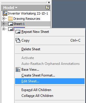
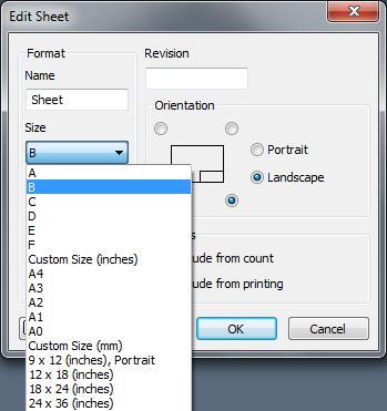
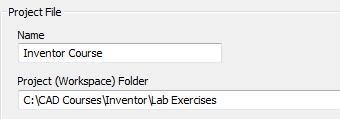
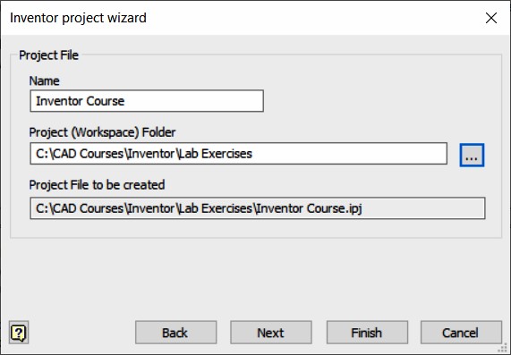
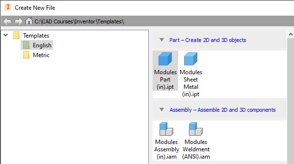
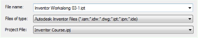
Using the NEW command, enable the English tab and select the temple file: Modules Assembly (in).iam. Save and name the assembly: Inventor workalong 22-1. (Figure Step 2)

Figure
Step 2
Step 3
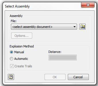
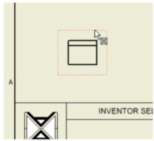
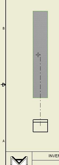
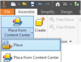
Enter the PLACE COMPONENT command. In the Place Component dialogue box insert part files: Inventor Workalong 22-1A.ipt and Inventor Workalong 22-1B.ipt into the assembly file. (Figure Step 3A and 3B)
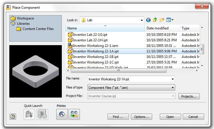
Figure Step 3A [Click to see image full size]
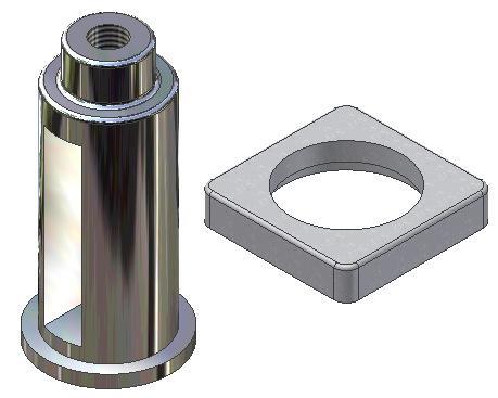
Figure Step 3B
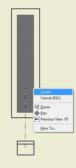
USER TIP: By default, the PLACE COMPONENT command places multiple parts. To insert the part more than once into the assembly file, click once for each part. Ensure that you move the cursor so you are not inserting one part on top of another one. When you have inserted the required part(s), press Esc to exit the command.
AUTHOR’S COMMENTS: Where you locate the parts is not important but ensure that you insert each part only once.
Step 4
Disable the grounding of part 22-1A and enable the grounding of part 22-1B. (Figure Step 4A, 4B, and 4C)
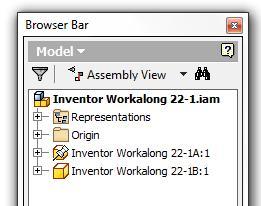
Figure Step 4A
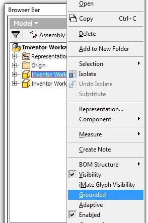
Figure Step 4B
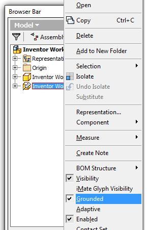
Figure Step 4C
Step 5
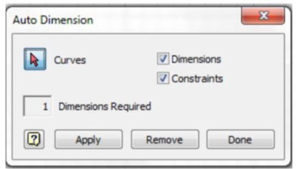
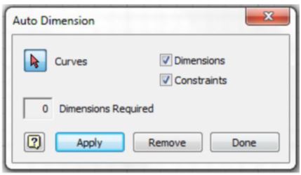
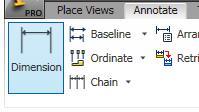
Enter the PLACE CONSTRAINT command. In the Place Constraint dialogue box set Type to Mate, Selections to 1, Offset to 0.000 and Solution to Mate. (Figure Step 5)
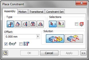
Figure Step 5
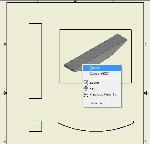
Step 6
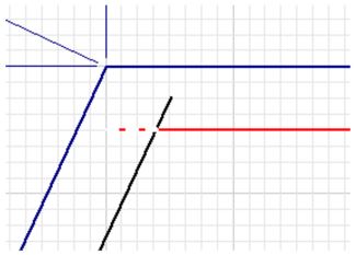
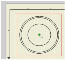
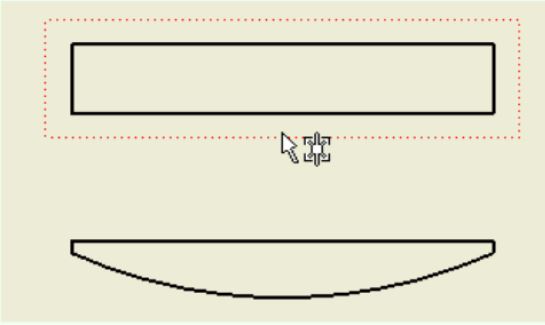
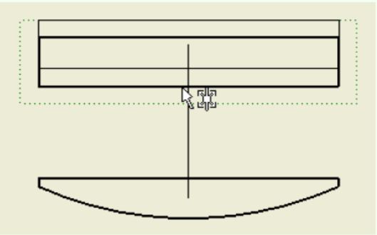
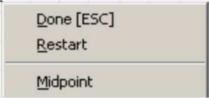
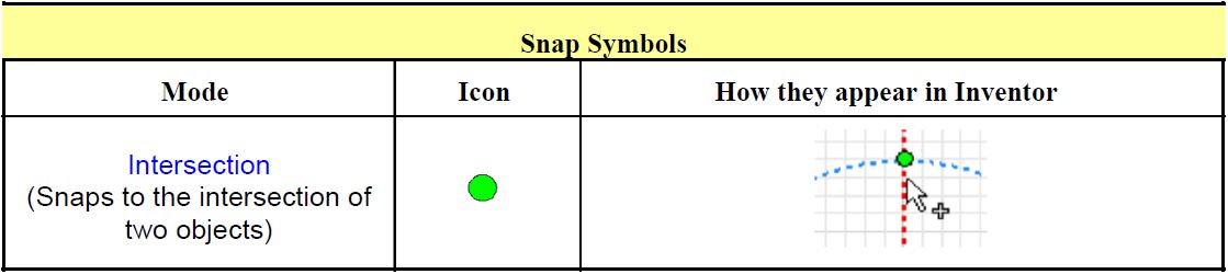
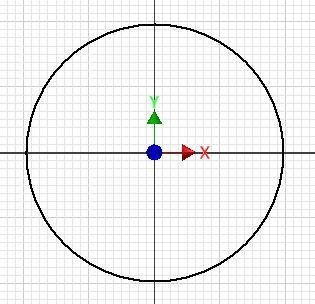
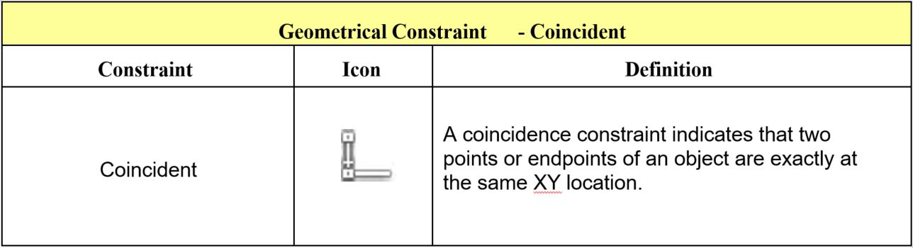
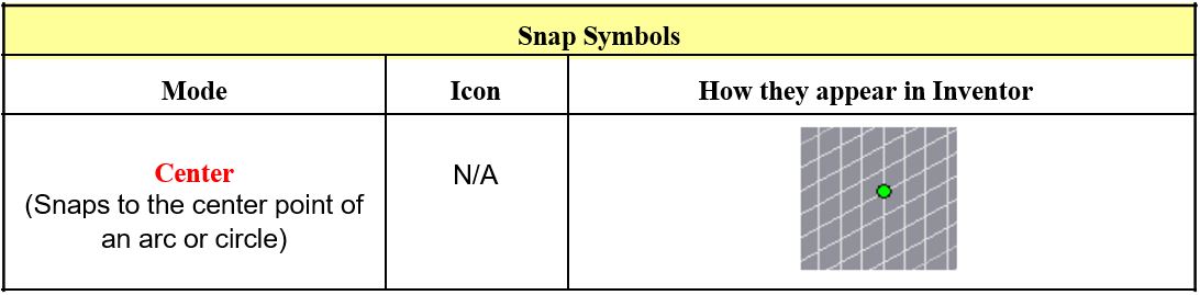
Move the cursor onto the part 22-1A and move it until the Centerline constraint symbol appears. When it displays as shown in the figure, select it. Move the cursor onto the part 22-1B and do the same. Part 22-1A will move onto Part 22-1B. Click Apply. (Figure Step 6A, 6B, and 6C)
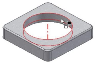
Figure Step 6A
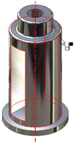
Figure Step 6B
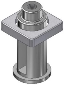
Figure Step 6C
AUTHOR’S COMMENTS: Since part 22-1B is the grounded part, it will remain stationary and part 22-1A will move.
Step 7
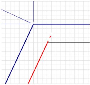
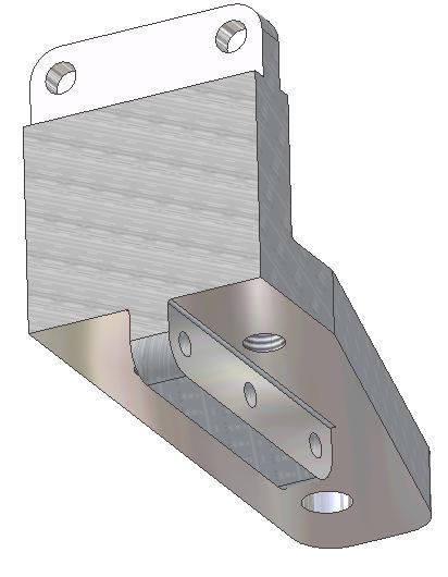
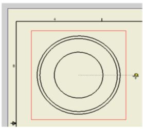
Move the cursor onto the top of the base on part 22-1B as shown in the figure. The mate arrow will display pointing up. Press F4 and rotate the model. Select the mate constraint for the bottom of the part 22-1A. (Figure Step 7A, 7B, and 7C)
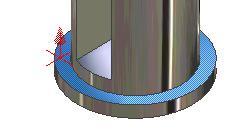
Figure Step 7A
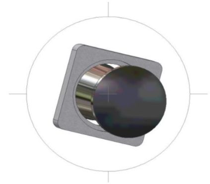
Figure Step 7B
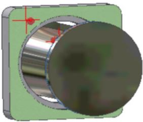
Figure Step 7C
Step 8
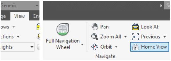
Press F6 to change the Home view. (Figure Step 8)
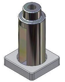
Figure Step 8
Step 9
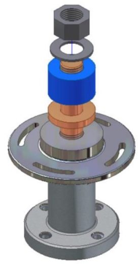
Enter the PLACE COMPONENT (P) command and insert part 22-1C, 22-1D, 22-1E, and 22-1F. Ensure that you place each part only once. (Figure Step 9)
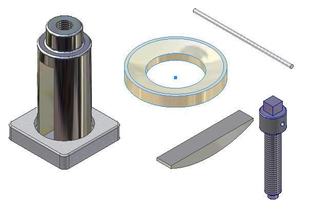
Figure Step 9
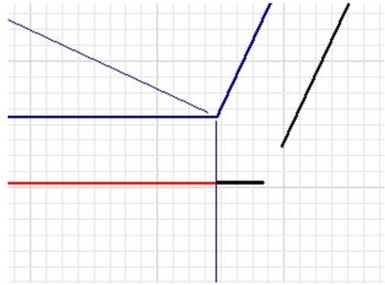
Step 10
Using what you just learned, assemble and constrain part 22-1C. (Figure Step 10)
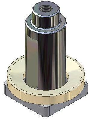
Figure Step 10
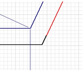
Step 11
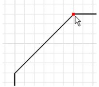
Using the PLACE CONSTRAINT command, constrain the arc in part 22-1D to the arc in part 22-1C. (Figure Step 11)
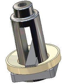
Figure Step 11
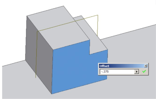
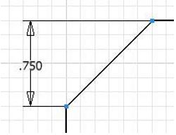
Step 12
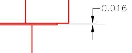
In the Offset box, set the offset to 0.015. Enable the Pick Part First box. See the Author’s Comments below. (Figure Step 12)
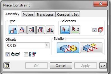
Figure Step 12
AUTHOR’S COMMENTS: The offset number was calculated by subtracting the width of the slot (0.75) and the width of the wedge (0.72) and then dividing by 2. That will centre the Wedge in the slot of the Post.
AUTHOR’S COMMENTS: When the Pick Part First box is enabled, the PLACE CONSTRAINT command allows the user to select the part first and then the constraint to be used. Sometimes it is easier to use the two pick method.
Step 13
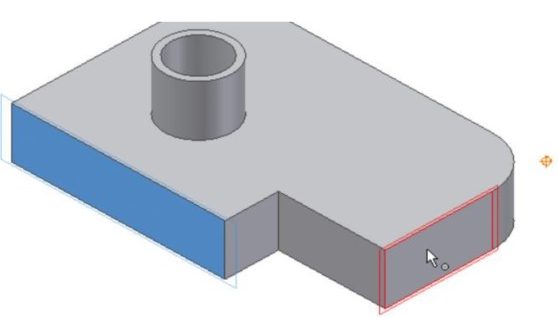
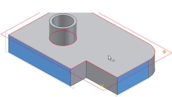
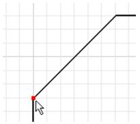
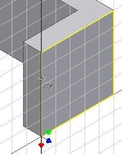
To constrain the wedge in the slot, select one side of the slot and one side of the wedge as the mate surfaces. (Figure Step 13A, 13B, and 13C)
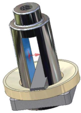
Figure Step 13A
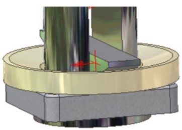
Figure Step 13B
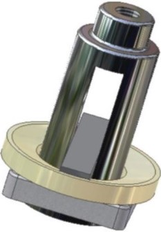
Figure Step 13C
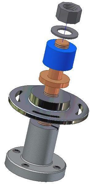
Step 14
Using what you just learned, constrain the last two parts to complete the assembly. (Figure Step 14)
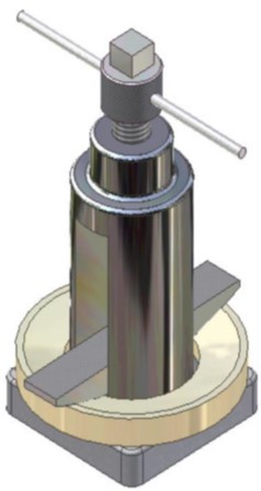
Figure Step 14
AUTHOR’S COMMENTS: You will have to constrain both parts with a centerline constraint and an offset constraint.
Step 15
Save and close the file.
Key Principles
- An assembly file contains the information required to assemble two or more part files to create the assembled model. An assembly file has the file extension .iam.
- An assembly file does do not contain any of the part files that are placed in the assembled model. It simply contains a reference to the part files. If an assembly file (.iam) is sent to a client or an associate, the part files (.ipt) that were placed in the assembly file must also be included otherwise they will not display when the assembly file is opened.
- By default, the first part that is placed into an assembly file will be grounded. A grounded part is a part that has all of it degrees of freedom removed and is fully constrained in that file.
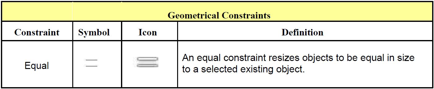
- There are many different constraints used when creating an assembly. A mate constraint constrains two assembled parts to one another by mating their centerlines and/or by mating a plane on one part to a plane on the other part.
Lab Exercise 22-1
Time allowed: 180 minutes.
| Part Name | Project | Units | Template | Color | Material |
| Inventor Lab 22-1 | Inventor Course | Millimeters | See Below | See Below | See Below |
Step 1
Create the following parts.
Step 2
Each part must have its own file. In each part, ensure that you do the following:
A Select your own location of X0Y0Z0.
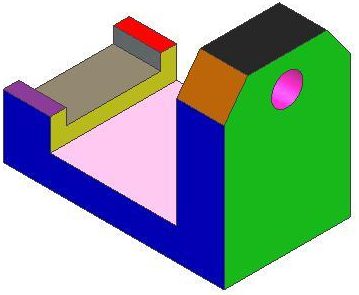
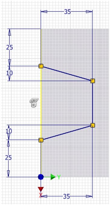
B Draw the necessary sketches and extrude or revolve them to produce the solid model shown. Apply all of the necessary geometrical and dimensional constraints to fully constrain all sketches. (Figure Step 2A and 2B)
C Apply the colour and material shown.
AUTHOR’S COMMENTS: Ensure that you draw each part in the correct orientation so that they can be assembled together.
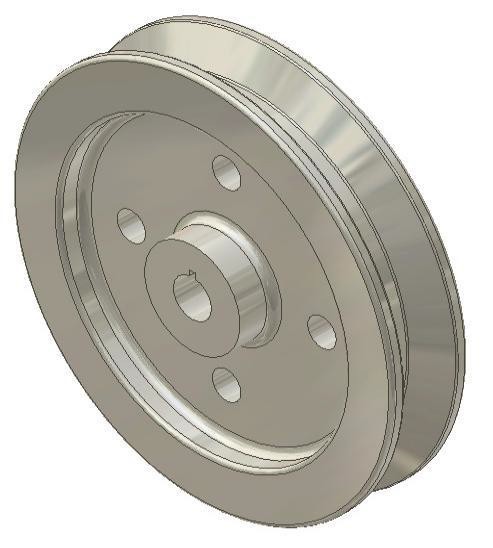
Part: Tire
Part Name: Inventor Lab 22-1A
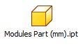
Template: Metric-Modules Part (mm).ipt
Color: Rubber – Green – Version 1.1
Material: Rubber
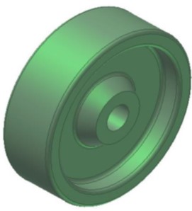
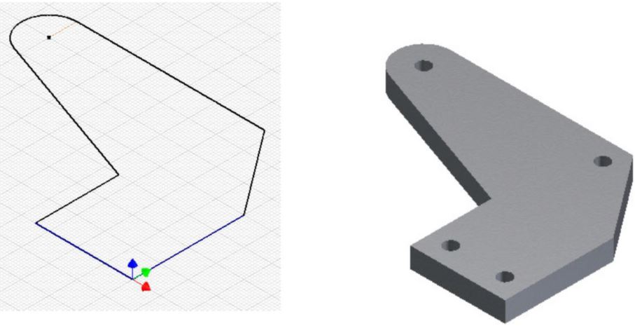
Figure Step 2A
Solid Model – Home View
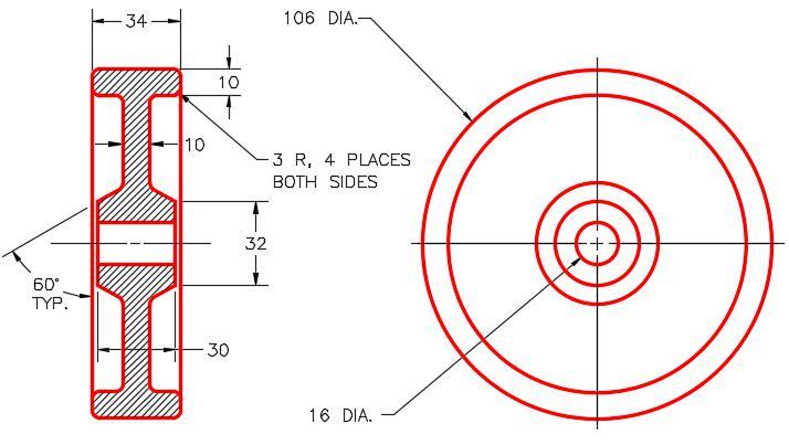
Figure Step 2B
Dimensioned Multiview Drawing
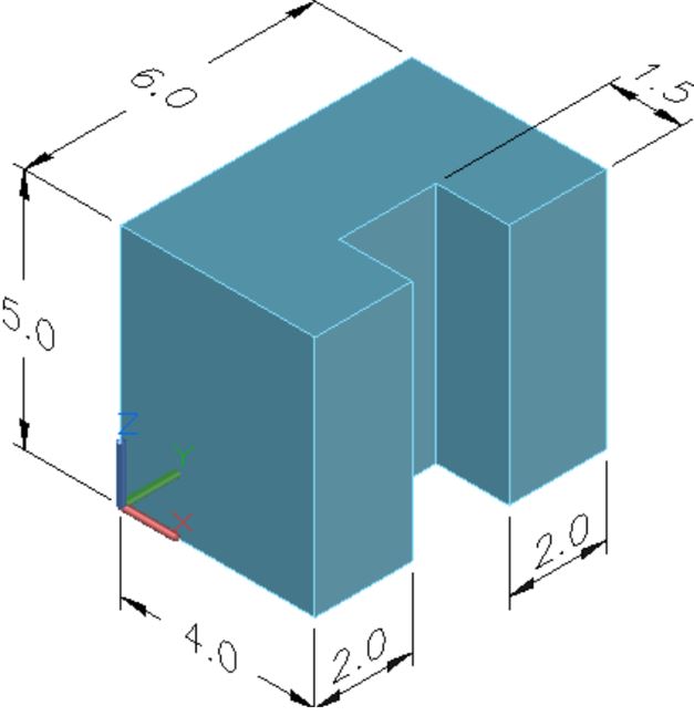
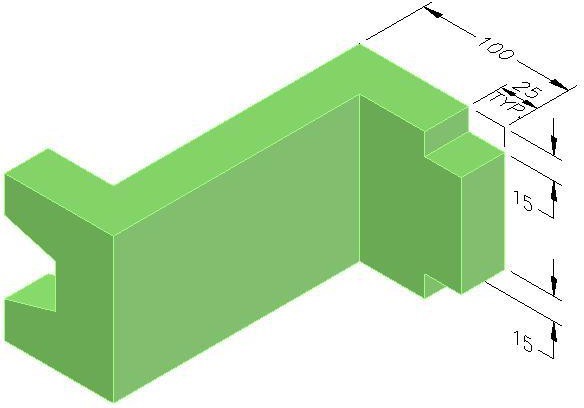
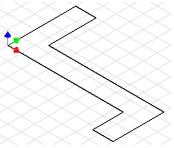
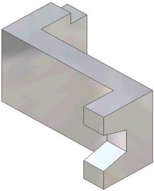
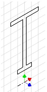
Part: Frame
Part Name: Inventor Lab 22-1B
Template: Metric-Modules Part (mm).ipt
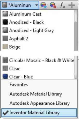
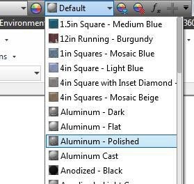
Color: Aluminum – Polished
Material: Steel (Figure Step 2C and 2D)
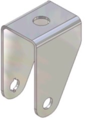
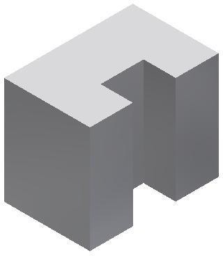
Figure Step 2C
Solid Model – Home View
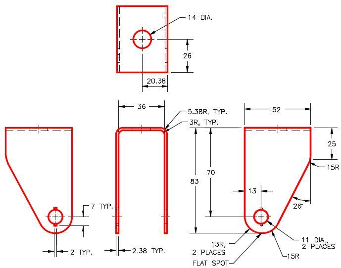
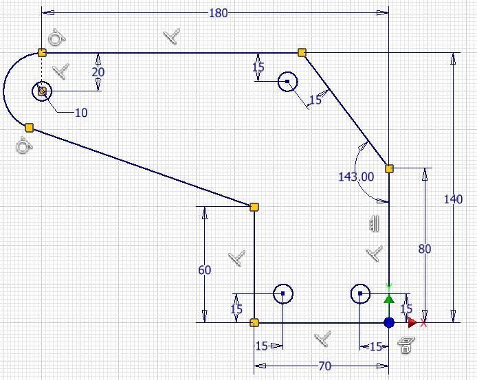
Figure Step 2D
Dimensioned Multiview drawing [Click to see image full size]
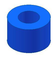
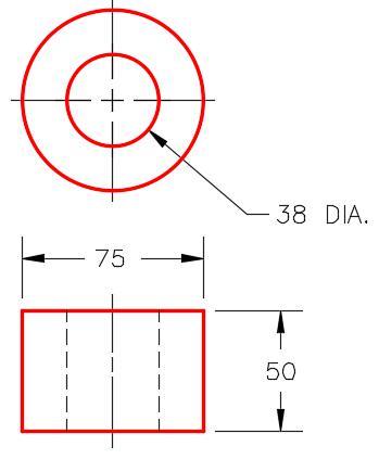
Part: Bushing
Part Name: Inventor Lab 22-1C
Template: Metric-Modules Part (mm).ipt
Color: Brass – Satin
Material: Brass (Figure Step 2E and 2F)
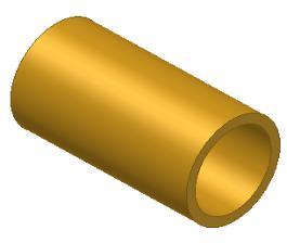
Figure Step 2E
Solid Model –
Home View
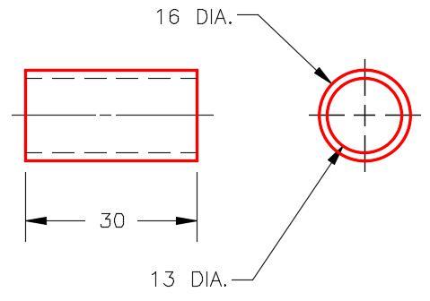
Figure Step 2F
Dimensioned Multiview Drawing
Part: Pin
Part Name: Inventor Lab 22-1D
Template: Metric-Modules Part (mm).ipt
Color: Semi – Polished
Material: Steel (Figure Step 2G, 2H and 2J)
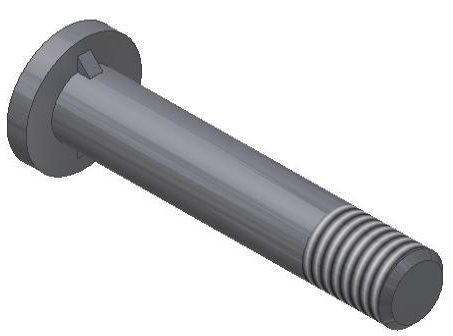
Figure Step 2G
Solid Model – Home View
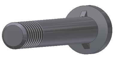
Figure Step 2H
Solid Model – Orbited View
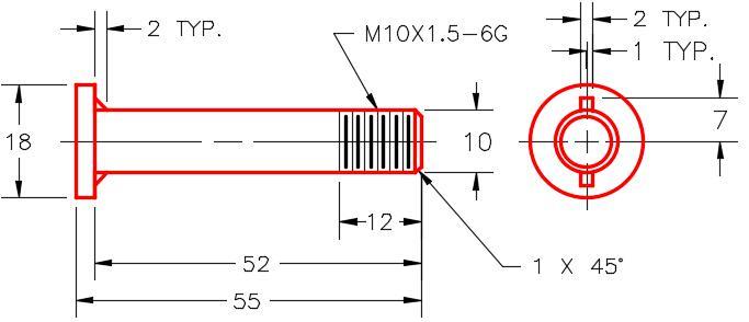
Figure Step 2J
Figure Step 2H
Solid Model – Orbited View
Dimensioned Multiview Drawing [Click to see image full size]
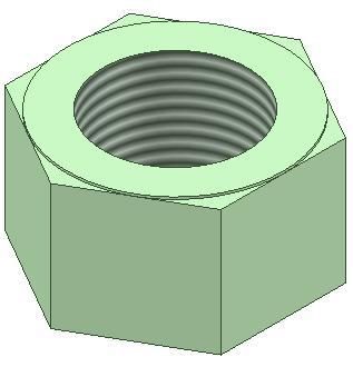
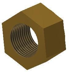
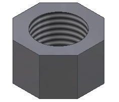
Part: 10 mm Nut
Part Name: Inventor Lab 22-1E
Template: Metric-Modules Part (mm).ipt
Color: Semi – Polished
Material: Steel (Figure Step 2K and 2L)
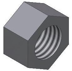
Figure Step 2K
Solid Model – Home View
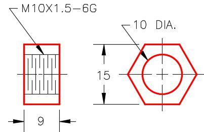
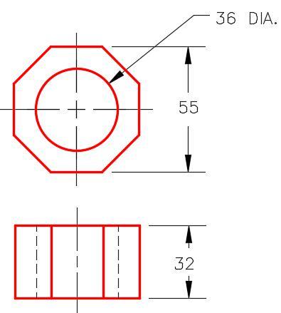
Figure Step 2L
Dimensioned Multiview Drawing
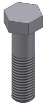
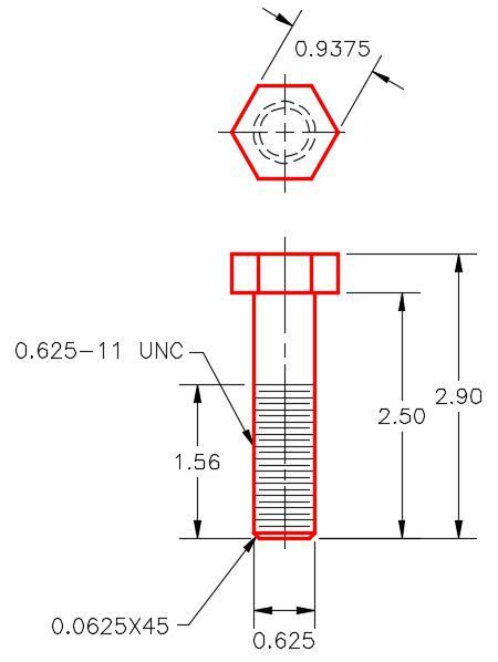
Part: Bolt
Part Name: Inventor Lab 22-1F
Template: Metric-Modules Part (mm).ipt
Color: Semi – Polished
Material: Steel (Figure Step 2M and 2N)
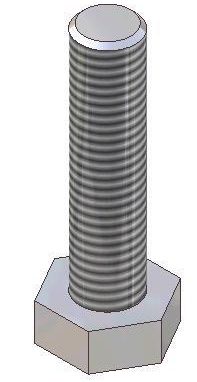
Figure Step 2M
Solid Model –
Home View
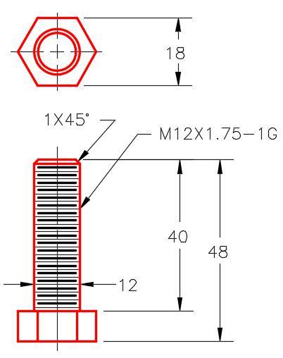
Figure Step 2N
Dimensioned Multiview Drawing
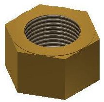
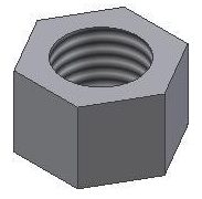
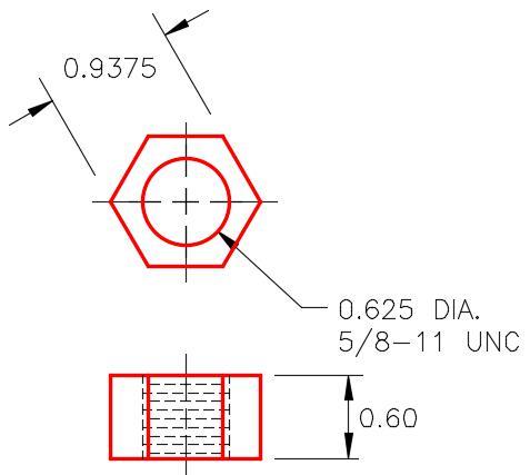
Part: 12 mm Nut
Part Name: Inventor Lab 22-1G
Template: Metric-Modules Part (mm).ipt
Color: Semi-Polished
Material: Steel (Figure Step 2P and 2Q)
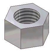
Figure Step 2P
Solid Model – Home
View
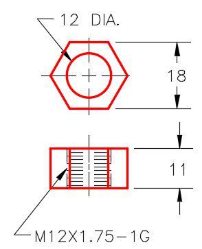
Figure Step 2Q
Dimensioned Multiview Drawing
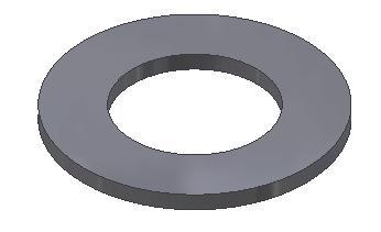
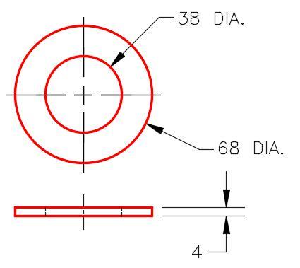
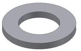
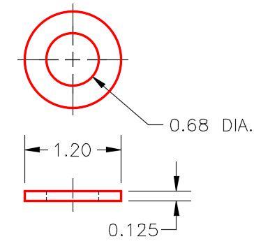
Part: Washer
Part Name: Inventor Lab 22-1H
Template: Metric-Modules Part (mm).ipt
Color: Semi-Polished
Material: Steel (Figure Step 2R and 2S)
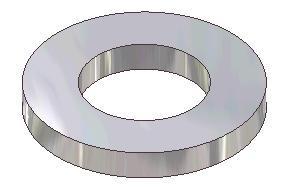
Figure Step 2R
Solid Model –
Home View
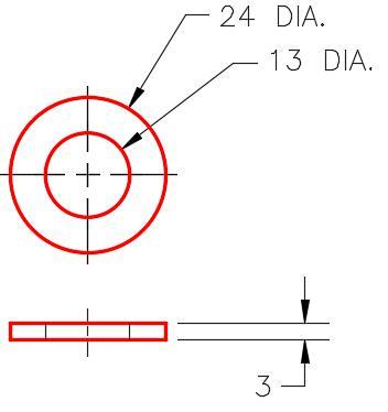
Figure Step 2S
Dimensioned Multiview Drawing
Step 3
Open a new assembly file.
Assembly: Caster
File Name: Inventor Lab 22-1.iam
Template: Metric – Modules Assembly (mm).iam
Step 4
Set the Tire as the grounded part.
Step 5
Start with assembling the Bushing into the Tire first. (Figure Step 5)
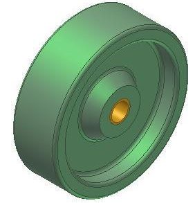
Figure Step 5
Step 6
Assemble the remaining parts to complete the assemble file. (Figure Step 6A and 6B)
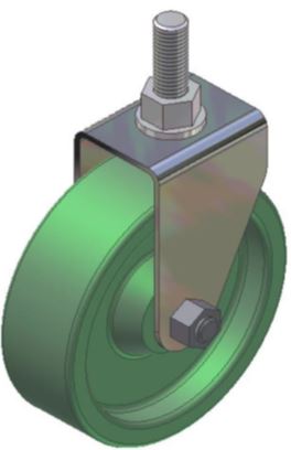
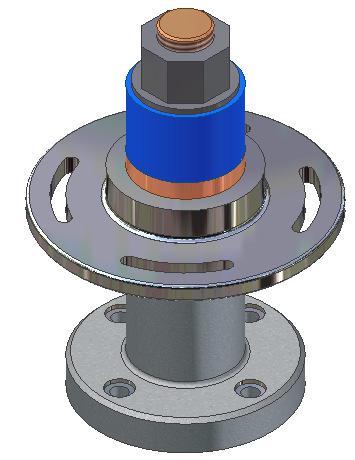
Figure Step 6A Assembled Model – Home View
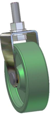
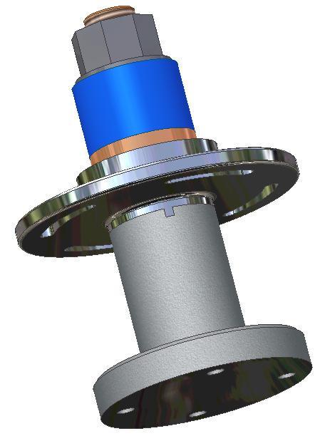
Figure Step 6B
Assembled Model –
Orbited View
AUTHOR’S COMMENTS: There are 2 washers. One above and one below the frame.


 Step 7